Product Overview of the STM32H743AII6TR
The STM32H743AII6TR represents a high-performance 32-bit microcontroller built on the ARM Cortex-M7 architecture, operating at frequencies up to 480 MHz. This device belongs to the STM32H7 family and is designed to address the demanding requirements of modern embedded systems across industrial, medical, consumer, and IoT applications. The microcontroller integrates up to 2 MB of flash memory and up to 1 MB of RAM, providing substantial resources for complex applications requiring real-time processing and extensive data handling.
The STM32H743AII6TR is manufactured using state-of-the-art technology and incorporates multiple power domains that can be independently managed, enabling flexible power optimization strategies. The device operates across a wide supply voltage range from 1.62 V to 3.6 V, making it suitable for battery-powered applications and systems with varying power supply constraints. With support for multiple low-power modes and comprehensive clock management capabilities, the STM32H743AII6TR delivers the performance necessary for computationally intensive tasks while maintaining energy efficiency.
Core Processing Architecture and Performance Capabilities of the STM32H743AII6TR
The STM32H743AII6TR is built around the ARM Cortex-M7 processor, a high-efficiency core specifically designed for embedded systems requiring both computational power and low power consumption. Operating at up to 480 MHz, the processor delivers 1027 DMIPS (Dhrystone 2.1), providing substantial processing capability for signal processing, control algorithms, and data-intensive operations.
The Cortex-M7 core in the STM32H743AII6TR features a double-precision floating-point unit (FPU) that supports both IEEE 754 single-precision and double-precision data types. This capability accelerates mathematical computations and reduces software complexity for applications involving complex calculations. The processor implements a six-stage dual-issue pipeline with dynamic branch prediction, enabling efficient instruction execution and reduced latency for time-critical operations.
The STM32H743AII6TR incorporates a memory protection unit (MPU) that manages CPU access rights and system resource attributes. The MPU can define up to 16 protected regions, each divisible into 8 independent subregions, with protection areas ranging from 32 bytes to 4 GB. This feature prevents untrusted programs from corrupting data used by the operating system or privileged tasks, enhancing system reliability and security.
The processor supports a comprehensive set of DSP (Digital Signal Processing) instructions, enabling efficient implementation of signal processing algorithms without requiring external specialized hardware. This capability makes the STM32H743AII6TR suitable for applications such as motor control, audio processing, and sensor data analysis.
Memory Architecture and Organization in the STM32H743AII6TR
The STM32H743AII6TR incorporates a sophisticated multi-level memory hierarchy designed to optimize both performance and power consumption. The device features up to 2 MB of embedded flash memory organized into two independent banks, each containing user flash memory blocks and system flash memory. This dual-bank architecture enables read-while-write operations, allowing the device to execute code from one bank while programming the other, a feature valuable for firmware updates without interrupting system operation.
The flash memory in the STM32H743AII6TR is organized as 256-bit words with integrated error correction code (ECC) protection. Each 256-bit word consists of 8 standard 32-bit words plus 10 ECC bits, implementing a SECDED (Single Error Correction, Double Error Detection) algorithm. This protection mechanism detects and corrects single-bit errors while identifying double-bit errors, maintaining data integrity throughout the device lifetime despite potential radiation-induced bit flips or manufacturing defects.
The STM32H743AII6TR provides up to 1 MB of RAM distributed across multiple memory domains. The device includes 192 KB of Tightly Coupled Memory (TCM) RAM, consisting of 64 KB of Instruction TCM (ITCM) and 128 KB of Data TCM (DTCM). These zero-wait-state memories connect directly to the processor through dedicated interfaces, enabling deterministic access times for time-critical routines and real-time interrupt service routines. The ITCM supports code execution with minimal latency, while the DTCM provides fast access for critical data structures and stack operations.
Beyond TCM memory, the STM32H743AII6TR incorporates up to 864 KB of user SRAM distributed across multiple domains (AXI-SRAM, SRAM1, SRAM2, SRAM3, and SRAM4), plus 4 KB of backup SRAM retained during low-power modes. The AXI-SRAM connects to the AXI bus on the D1 domain, supporting high-bandwidth transfers for DMA operations. Domain-specific SRAM allocations enable optimized memory access patterns and power management strategies.
Power Management and Supply Architecture of the STM32H743AII6TR
The STM32H743AII6TR implements a sophisticated power management system with three independent power domains (D1, D2, and D3) that can be individually clock-gated or powered down. This architecture enables selective power control, allowing portions of the device to remain active while others enter low-power states, optimizing energy consumption for applications with varying operational requirements.
The device accepts external power supplies ranging from 1.62 V to 3.6 V through dedicated VDD pins. An integrated voltage regulator (LDO) generates the core voltage (VCORE) from the external supply, with configurable output levels supporting six power scaling ranges. In Run mode, four scaling levels (VOS0 through VOS3) provide performance-consumption trade-offs, with VOS0 offering boosted performance at maximum power consumption, while VOS3 optimizes for low-power operation. In Stop mode, three additional scaling levels (SVOS3 through SVOS5) enable peripheral operation with minimal power consumption.
The STM32H743AII6TR incorporates multiple power supervisors monitoring the supply voltage. The Power-On Reset (POR) supervisor ensures the device remains in reset when VDD is below a fixed threshold, preventing erratic behavior during power-up. The Power-Down Reset (PDR) supervisor generates a reset when VDD drops below a threshold, protecting against data corruption during power loss. A Brownout Reset (BOR) circuit provides three configurable thresholds (2.1 V to 2.7 V) through option bytes, enabling application-specific reset behavior.
The device features a dedicated VBAT domain supplied by a backup battery pin, enabling retention of backup SRAM and RTC functionality during main power loss. A backup regulator (~0.9 V) maintains the VBAT domain, supporting battery-backed operation for real-time clock and data retention applications. The STM32H743AII6TR also includes dedicated USB power pins with an internal 3.3 V regulator, allowing independent USB supply management.
Low-power modes in the STM32H743AII6TR include Sleep (CPU clock stopped), Stop (system clock stopped), Standby (system powered down), and VBAT mode (backup domain only). Wakeup from these modes can be triggered by external interrupts, RTC events, or specific peripheral activities, enabling responsive low-power operation. Typical standby current consumption reaches 2.95 µA with backup SRAM off and RTC/LSE on, making the device suitable for battery-powered applications requiring extended operational lifetime.
Clock Generation and Management in the STM32H743AII6TR
The STM32H743AII6TR provides comprehensive clock generation and management capabilities supporting multiple clock sources and flexible frequency configurations. The device integrates four internal oscillators: a 64 MHz high-speed internal oscillator (HSI), a 48 MHz HSI48 for USB applications, a 4 MHz low-power oscillator (CSI), and a 32 kHz low-speed oscillator (LSI). These internal sources enable operation without external components, simplifying board design and reducing component count.
External clock sources supported by the STM32H743AII6TR include a 4-48 MHz high-speed external (HSE) oscillator for precise system clock generation and a 32.768 kHz low-speed external (LSE) oscillator for real-time clock applications. The device accommodates both crystal resonators and external clock signals, with integrated oscillator startup detection and stabilization monitoring.
The STM32H743AII6TR incorporates three Phase-Locked Loops (PLLs) enabling flexible frequency synthesis. One PLL generates the system clock, while two additional PLLs provide kernel clocks for peripherals. Each PLL supports fractional mode operation, enabling fine-grained frequency adjustment for applications requiring precise clock frequencies. The PLLs support wide and medium VCO frequency ranges, accommodating diverse input frequencies and output requirements.
The device implements a Reset and Clock Controller (RCC) managing clock distribution to all peripherals and domains. Individual clock gating for each peripheral enables dynamic power management, allowing unused peripherals to be disabled, reducing overall power consumption. The RCC supports multiple clock domains with independent prescalers, enabling optimized clock frequencies for different functional blocks.
Communication Interfaces Supported by the STM32H743AII6TR
The STM32H743AII6TR integrates an extensive array of communication interfaces supporting diverse connectivity requirements. The device provides four I2C interfaces supporting Standard-mode (100 kbit/s), Fast-mode (400 kbit/s), and Fast-mode Plus (1 Mbit/s) operation. These interfaces include hardware support for System Management Bus (SMBus) and Power System Management Protocol (PMBus) specifications, with programmable analog and digital noise filters for robust operation in noisy environments.
Serial communication capabilities include four USART interfaces and four UART interfaces supporting asynchronous communication at speeds up to 12.5 Mbit/s. The USARTs provide additional features including ISO 7816 Smartcard mode, LIN Master/Slave capability, and IrDA support. A dedicated Low-Power UART (LPUART) operates independently from the main clock, enabling low-power serial communication even in Stop mode. All USART/UART interfaces embed transmit and receive FIFOs, reducing CPU interrupt overhead and improving throughput.
The STM32H743AII6TR features six SPI interfaces supporting Master and Slave modes with speeds up to 150 Mbit/s. Three SPI interfaces can be multiplexed with I2S audio interfaces, supporting 16-bit and 32-bit audio resolutions with sampling frequencies from 8 kHz to 192 kHz. The I2S interfaces can be clocked by a dedicated internal audio PLL or external clock, enabling audio class accuracy and synchronization with external audio systems.
Four Serial Audio Interfaces (SAI) provide flexible audio protocol support including I2S, LSB/MSB-justified, PCM/DSP, TDM, and AC'97 formats. The SAI blocks support up to 192 kHz sampling rates and can operate synchronously or asynchronously, enabling complex audio system implementations. An embedded PDM interface supports up to six microphones, enabling multi-microphone audio capture with hardware PDM-to-PCM conversion.
The STM32H743AII6TR includes two SD/SDIO/MMC host interfaces supporting MultiMediaCard System Specification Version 4.51 and SD memory card specifications version 4.1. These interfaces support 1-bit, 4-bit, and 8-bit data bus modes with speeds up to 125 MHz, enabling high-speed data transfer with memory cards and SDIO peripherals.
Ethernet connectivity is provided through an IEEE 802.3-2002-compliant MAC interface supporting both MII and RMII physical interfaces. The device supports 10 and 100 Mbit/s operation with dedicated DMA controller for high-speed transfers. Hardware support for precision time protocol (PTP) according to IEEE 1588 enables time-synchronized networking applications.
The STM32H743AII6TR provides two USB OTG interfaces: OTG-HS1 supporting both high-speed (480 Mbit/s) and full-speed (12 Mbit/s) operation, and OTG-HS2 supporting full-speed operation only. Both interfaces integrate full-speed transceivers and support the USB 2.0 specification with OTG 2.0 capability. OTG-HS1 features a UTMI low-pin interface (ULPI) for high-speed operation with external PHY devices. The USB controllers support suspend/resume, session request protocol (SRP), and host negotiation protocol (HNP).
CAN communication is supported through two FDCAN interfaces compliant with ISO 11898-1 (CAN 2.0) and CAN FD specifications. FDCAN1 additionally supports time-triggered CAN (TT-FDCAN) specified in ISO 11898-4, enabling event-synchronized time-triggered communication with global system time and clock drift compensation. A shared 10 KB message RAM implements filters, receive FIFOs, and transmit buffers for both CAN modules.
Analog Signal Processing Capabilities of the STM32H743AII6TR
The STM32H743AII6TR incorporates comprehensive analog signal processing capabilities supporting diverse sensor and signal conditioning applications. The device features three 16-bit analog-to-digital converters (ADCs) with up to 36 channels and maximum sampling rates of 3.6 MSPS. The ADCs support multiple resolution modes (6-bit through 16-bit) enabling trade-offs between resolution and sampling speed. Programmable sampling times and configurable input ranges accommodate various sensor types and signal levels.
The ADCs in the STM32H743AII6TR implement successive approximation architecture with integrated sample-and-hold circuits. Each ADC includes an analog watchdog feature enabling interrupt generation when conversion results exceed programmed thresholds, supporting autonomous monitoring without CPU intervention. The ADCs support both single and continuous conversion modes, with software or hardware triggering from timers or external signals.
Two 12-bit digital-to-analog converters (DACs) provide analog output capabilities with 1 MHz update rates. The DACs support both buffered and unbuffered output modes, with the buffered mode reducing output impedance for direct load driving. Programmable output ranges and DMA support enable efficient waveform generation and signal synthesis.
The STM32H743AII6TR includes two ultra-low-power comparators with programmable hysteresis and multiple input/output configurations. These comparators support window comparison modes and can generate interrupts or trigger other peripherals on comparison events. Two operational amplifiers with 7.3 MHz bandwidth support configurable gain settings (2 to 16 for non-inverting, -1 to -15 for inverting configurations), enabling flexible analog signal conditioning.
A Digital Filter for Sigma-Delta Modulators (DFSDM) with four filter modules and eight input channels supports external sigma-delta modulator interfacing and PDM microphone input. The DFSDM implements Sinc filters with configurable order (1-5) and oversampling ratios (1-1024), delivering up to 24-bit output resolution. Analog watchdog functionality and short-circuit detection enable robust sensor interface implementation.
An integrated temperature sensor provides on-chip temperature monitoring with calibration values stored in option bytes. The temperature sensor supports continuous monitoring and can trigger interrupts when temperature exceeds programmed thresholds, enabling thermal management and protection functions.
Timer and Control Functions in the STM32H743AII6TR
The STM32H743AII6TR provides comprehensive timing and control capabilities through 22 timers and watchdog functions. A high-resolution timer (HRTIM1) delivers 2.1 nanosecond resolution through a 480 MHz digital kernel, enabling precise PWM generation and phase-shifted pulse control. The HRTIM1 consists of one master timer and five slave timers, providing 10 high-resolution outputs that can be coupled for deadtime insertion. This timer supports complex converter topologies including LLC, full-bridge phase-shifted, buck, and boost converters.
Two advanced-control timers (TIM1, TIM8) function as three-phase PWM generators with complementary outputs and programmable deadtime insertion. These timers support input capture, output compare, and PWM generation in edge-aligned or center-aligned modes. Four full-featured general-purpose timers (TIM2-TIM5) provide 32-bit or 16-bit counters with four independent channels each, supporting input capture, output compare, PWM, and one-pulse modes. Six additional general-purpose timers (TIM12-TIM17) provide 16-bit counters with one or two independent channels.
Two basic timers (TIM6, TIM7) primarily serve as DAC triggers and waveform generators, supporting 16-bit time base functionality. Five low-power timers (LPTIM1-LPTIM5) operate independently from the main clock, enabling operation in Stop mode when clocked by LSE or LSI. These timers support 16-bit up-counting with configurable output modes (pulse or PWM) and external trigger inputs.
The STM32H743AII6TR includes two watchdog timers: an independent watchdog based on a 12-bit downcounter clocked from an independent 32 kHz RC oscillator, and a window watchdog based on a 7-bit downcounter with early warning interrupt capability. A SysTick timer provides a 24-bit downcounter dedicated to real-time operating systems.
Advanced Peripheral Features of the STM32H743AII6TR
The STM32H743AII6TR incorporates several advanced peripheral features supporting specialized applications. A camera interface (DCMI) supports 8-bit to 14-bit parallel data from CMOS sensors with pixel clock rates up to 80 MHz, enabling video data capture at rates up to 140 Mbyte/s. The interface supports programmable polarity for pixel clock and synchronization signals, with automatic image cropping capabilities.
An LCD-TFT display controller (available on STM32H743xI/G variants) provides 24-bit parallel RGB output supporting display resolutions up to XGA (1024x768). The controller features two display layers with dedicated FIFOs, color lookup tables (CLUT) supporting 256 colors per layer, and flexible blending between layers using per-pixel or constant alpha values. Up to four programmable interrupt events enable display synchronization with application logic.
A JPEG codec (available on STM32H743xI/G variants) provides hardware-accelerated JPEG encoding and decoding according to ISO/IEC 10918-1 specification. The codec supports 8-bit/channel pixel depths with single-clock-per-pixel operation, programmable quantization and Huffman tables, and full JPEG header management.
A Chrom-ART graphical hardware accelerator (DMA2D) reduces CPU load for graphics operations through dedicated DMA functionality. This accelerator supports color format conversion, image rotation, and blending operations, offloading computationally intensive graphics tasks from the main processor.
An SPDIFRX receiver interface supports S/PDIF signal reception compliant with IEC-60958 and IEC-61937 standards, enabling stereo streams from 32 to 192 kHz and compressed multi-channel surround sound. Automatic symbol rate detection and Manchester decoding simplify integration with audio systems.
A Single Wire Protocol Master Interface (SWPMI) implements the Contactless Frontend (CLF) interface specified in ETSI TS 102 613, supporting full-duplex communication at configurable bitrates up to 2 Mbit/s with automatic SOF, EOF, and CRC handling.
Four DMA controllers offload data transfer operations from the CPU. A high-speed master DMA (MDMA) with linked list support handles high-bandwidth transfers. Two dual-port DMAs with FIFO support peripheral-to-memory and memory-to-peripheral transfers. A basic DMA with request router capabilities handles simpler transfer scenarios. These controllers enable efficient data movement without CPU intervention, reducing power consumption and improving system responsiveness.
Input/Output Configuration and Characteristics of the STM32H743AII6TR
The STM32H743AII6TR provides up to 168 I/O ports with interrupt capability, distributed across multiple GPIO ports (A through K). Each GPIO pin supports configurable input/output modes including push-pull, open-drain, and floating configurations with optional pull-up or pull-down resistors. GPIO pins can be configured as analog inputs to reduce power consumption when not actively used.
The I/O system in the STM32H743AII6TR supports multiple voltage levels through separate I/O supply pins (VDDIO1, VDDIO2, VDDIO3), enabling mixed-voltage interfacing. Standard I/O pins support 3.3 V operation with CMOS and TTL compatibility. Specialized I/O pins (PC13, PC14, PC15, PI8) operate from the VBAT domain, enabling GPIO control during low-power modes.
GPIO output drivers can source or sink up to 8 mA at standard voltage levels, with relaxed specifications supporting up to 20 mA operation. Output timing characteristics include programmable slew rates through the HSLV (High-Speed Low Voltage) option, enabling EMI optimization for different supply voltages. Output voltage levels meet JEDEC standards JESD36 and JESD52 for TTL and CMOS compatibility.
The STM32H743AII6TR implements an I/O compensation cell enabling optimized output timing across supply voltage and temperature variations. This compensation system maintains consistent output characteristics despite environmental changes, improving signal integrity and reducing timing uncertainty.
Packaging Options and Physical Specifications of the STM32H743AII6TR
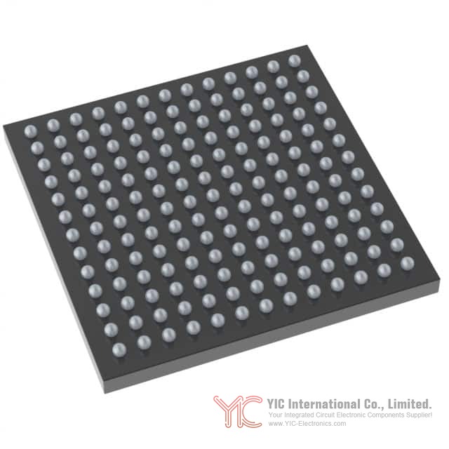
The STM32H743AII6TR is available in eight package options accommodating diverse application requirements. The LQFP100 package (14 x 14 mm) provides 100 pins in a low-profile quad flat package suitable for space-constrained applications. The TFBGA100 package (8 x 8 mm) offers a compact ball grid array option with 0.8 mm pitch.
The LQFP144 package (20 x 20 mm) provides 144 pins enabling access to additional peripherals. The UFBGA169 package (7 x 7 mm) offers a compact 0.5 mm pitch ball grid array with 169 balls. The LQFP176 package (24 x 24 mm) provides 176 pins in a larger quad flat package. The LQFP208 package (28 x 28 mm) offers the maximum pin count in quad flat package format.
The UFBGA176+25 package (10 x 10 mm) provides 201 balls (176 + 25 spare) with 0.65 mm pitch. The TFBGA240+25 package (14 x 14 mm) offers the highest pin count with 265 balls (240 + 25 spare) in a 0.8 mm pitch ball grid array.
All packages are ECOPACK2 compliant, meeting environmental and lead-free requirements. Package selection depends on application requirements for pin count, board space, and thermal management. Larger packages provide access to additional peripherals and improved thermal characteristics through increased surface area.
Electrical Performance and Operating Conditions of the STM32H743AII6TR
The STM32H743AII6TR operates across a wide temperature range from -40°C to +85°C (or -40°C to +125°C for extended temperature variants), supporting diverse environmental conditions. The device maintains specified performance across supply voltages from 1.62 V to 3.6 V, with the LQFP100 package requiring minimum 1.71 V due to internal PDR_ON pin connection.
Run mode current consumption varies with operating frequency and code location. Typical consumption at 400 MHz with code running from ITCM reaches approximately 150 mA, while operation from flash memory with cache enabled consumes approximately 180 mA. Sleep mode reduces consumption to approximately 50 mA, while Stop mode achieves approximately 10 mA. Standby mode with backup SRAM off and RTC/LSE on consumes only 2.95 µA, enabling extended battery operation.
The STM32H743AII6TR implements comprehensive electrical protection including ESD (Electrostatic Discharge) protection rated at 4 kV for human body model and 8 kV for charged device model. Latchup immunity testing confirms robustness against supply overvoltage and current injection events. EMC (Electromagnetic Compatibility) characterization demonstrates functional immunity to ESD, fast transient bursts, and electromagnetic interference.
Flash memory endurance exceeds 100,000 erase cycles with data retention exceeding 20 years at 55°C. The device supports in-application programming through multiple boot modes including USART, I2C, SPI, and USB-DFU interfaces, enabling field firmware updates without external programming equipment.
Conclusion
The STM32H743AII6TR represents a comprehensive high-performance microcontroller solution addressing the demanding requirements of modern embedded systems. The combination of a 480 MHz ARM Cortex-M7 processor, extensive memory resources, sophisticated power management, and diverse peripheral interfaces enables implementation of complex applications spanning industrial control, medical devices, consumer electronics, and IoT systems. The device's flexible packaging options, robust electrical characteristics, and comprehensive development support make it suitable for applications requiring both computational performance and energy efficiency. The integration of advanced features such as high-resolution timers, graphics acceleration, and specialized audio interfaces positions the STM32H743AII6TR as a versatile platform for next-generation embedded applications.
Frequently Asked Questions (FAQ)
- Q1. What is the maximum operating frequency of the STM32H743AII6TR, and how does it compare to other microcontrollers in its class?
-
- A1. The STM32H743AII6TR operates at a maximum frequency of 480 MHz, delivering 1027 DMIPS (Dhrystone 2.1) performance. This frequency is achieved through the ARM Cortex-M7 core with its six-stage dual-issue pipeline and dynamic branch prediction. The 480 MHz operation is available on revision V devices and represents one of the highest clock frequencies in the STM32H7 family, enabling computationally intensive applications such as real-time signal processing, motor control algorithms, and complex data analysis without requiring external coprocessors.
- Q2. How much flash memory and RAM does the STM32H743AII6TR provide, and how is this memory organized?
-
- A2. The STM32H743AII6TR provides up to 2 MB of flash memory organized into two independent banks, each supporting read-while-write operations. The device includes up to 1 MB of RAM distributed across multiple domains: 192 KB of Tightly Coupled Memory (64 KB ITCM + 128 KB DTCM), up to 864 KB of user SRAM across multiple domains, and 4 KB of backup SRAM. The TCM memory provides zero-wait-state access for time-critical code and data, while the distributed SRAM organization enables optimized memory access patterns and independent power management of different memory domains.
- Q3. What power supply voltage range does the STM32H743AII6TR support, and what are the implications for system design?
-
- A3. The STM32H743AII6TR operates across a supply voltage range from 1.62 V to 3.6 V, with the LQFP100 package requiring minimum 1.71 V. This wide voltage range enables operation from single-cell lithium batteries (3.0-3.6 V), dual-cell alkaline batteries (3.0 V), or regulated supplies. The device integrates an internal voltage regulator with configurable output levels supporting six power scaling ranges, enabling dynamic voltage and frequency scaling for power optimization. External power supervisors can extend the minimum voltage to 1.62 V, supporting ultra-low-power battery applications.
- Q4. How many communication interfaces does the STM32H743AII6TR provide, and which protocols are supported?
-
- A4. The STM32H743AII6TR integrates 35 communication peripherals including four I2C interfaces (Standard/Fast/Fast-mode Plus), four USART and four UART interfaces (up to 12.5 Mbit/s), six SPI interfaces (up to 150 Mbit/s), three I2S audio interfaces, four SAI interfaces, two SD/SDIO/MMC interfaces, two CAN FD interfaces, two USB OTG interfaces, one Ethernet MAC interface, and one SPDIFRX interface. This comprehensive peripheral set enables integration with diverse external devices and systems without requiring external interface controllers.
- Q5. What low-power modes are available in the STM32H743AII6TR, and how do they affect system responsiveness?
-
- A5. The STM32H743AII6TR supports multiple low-power modes: Sleep (CPU clock stopped, ~50 mA typical), Stop (system clock stopped, ~10 mA typical), Standby (system powered down, ~2.95 µA typical), and VBAT mode (backup domain only). Wakeup times from these modes range from microseconds (Sleep) to milliseconds (Standby), enabling responsive operation despite low power consumption. The device can wake from low-power modes through external interrupts, RTC events, or specific peripheral activities, allowing applications to balance power consumption with responsiveness requirements.
- Q6. What analog signal processing capabilities does the STM32H743AII6TR provide for sensor interfacing?
-
- A6. The STM32H743AII6TR features three 16-bit ADCs with up to 36 channels and 3.6 MSPS sampling rate, two 12-bit DACs with 1 MHz update rate, two ultra-low-power comparators, two operational amplifiers, and a DFSDM with four filter modules supporting sigma-delta modulator and PDM microphone interfacing. These analog peripherals enable direct sensor connection without external signal conditioning circuits for many applications. The integrated temperature sensor provides on-chip thermal monitoring, while programmable analog watchdog functions enable autonomous threshold monitoring.
- Q7. How does the STM32H743AII6TR support real-time applications requiring precise timing?
-
- A7. The STM32H743AII6TR provides a high-resolution timer (HRTIM1) with 2.1 nanosecond resolution, enabling precise PWM generation and phase-shifted pulse control. The device includes 22 timers total, with advanced-control timers supporting complementary PWM outputs with programmable deadtime insertion. Tightly Coupled Memory (TCM) provides zero-wait-state access for time-critical code, while the memory protection unit enables isolation of real-time tasks. Multiple independent clock sources and flexible interrupt handling support deterministic real-time operation.
- Q8. What package options are available for the STM32H743AII6TR, and how should the selection be made?
-
- A8. The STM32H743AII6TR is available in eight packages ranging from LQFP100 (100 pins, 14x14 mm) to TFBGA240+25 (265 balls, 14x14 mm). Package selection depends on application requirements for pin count, board space, thermal management, and cost. Smaller packages (LQFP100, TFBGA100, UFBGA169) suit space-constrained applications, while larger packages (LQFP208, TFBGA240+25) provide maximum peripheral access and improved thermal characteristics. BGA packages offer superior thermal performance and higher pin density compared to quad flat packages.
- Q9. What security features does the STM32H743AII6TR provide for protecting intellectual property and system integrity?
-
- A9. The STM32H743AII6TR incorporates a memory protection unit (MPU) defining up to 16 protected regions with configurable access rights, preventing unauthorized code execution and data access. Read-out protection (ROP) and PC-relative read-out protection (PC-ROP) prevent unauthorized flash memory access. Active tamper detection with three anti-tamper pins enables detection of physical tampering attempts. The device supports secure boot through configurable boot addresses and option bytes, enabling implementation of secure firmware update mechanisms.
- Q10. How does the STM32H743AII6TR support graphics and display applications?
-
- A10. The STM32H743AII6TR (STM32H743xI/G variants) includes an LCD-TFT display controller supporting resolutions up to XGA (1024x768) with 24-bit RGB output. The controller features two display layers with dedicated FIFOs, color lookup tables supporting 256 colors per layer, and flexible alpha blending. A Chrom-ART graphical hardware accelerator (DMA2D) offloads graphics operations including color format conversion and image rotation. A JPEG codec provides hardware-accelerated JPEG encoding and decoding, enabling efficient image processing without CPU intervention.
- Q11. What development and debugging support is available for the STM32H743AII6TR?
-
- A11. The STM32H743AII6TR provides comprehensive debug infrastructure including JTAG and Serial-Wire Debug (SWD) interfaces supporting industry-standard debugging tools. A 4 KB embedded trace buffer enables code execution tracing and analysis. The device supports software instrumentation through breakpoint debugging and trigger input/output. ARM CoreSight debug and trace components enable integration with professional development environments. Multiple boot modes (USART, I2C, SPI, USB-DFU) support in-application programming for field firmware updates.
- Q12. What thermal management considerations apply to the STM32H743AII6TR?
-
- A12. The STM32H743AII6TR operates across junction temperatures from -40°C to +85°C (or -40°C to +125°C for extended variants). Thermal characteristics vary by package, with larger packages (LQFP208, TFBGA240+25) providing superior thermal performance through increased surface area. Thermal resistance values range from approximately 40°C/W (LQFP100) to 15°C/W (TFBGA240+25).