Product Overview: RxxPxx/R Series Reinforced Isolation DC/DC Converters
The RxxPxx/R series represents a family of isolated DC/DC converters designed by Recom Power to address the stringent requirements of safety-critical applications. These 1-watt converters deliver a single output of 5V at up to 400mA, operating from input voltage ranges between 21.6V and 26.4V. The fundamental design philosophy centers on providing reinforced galvanic isolation while maintaining compact form factors suitable for modern electronic systems.
The RxxPxx/R series distinguishes itself through a unique reinforced isolation transformer system that achieves isolation ratings of either 6.4kVDC or 8kVDC for one second duration. This architecture enables the converters to meet multiple international safety standards simultaneously, including UL/CSA60950-1, IEC/EN60950-1, UL/ES/CSA60601-1, IEC/EN60601-1, and IEC/EN61010-1 certifications. The breadth of these certifications reflects the converter's suitability across diverse application domains ranging from laboratory equipment to medical devices.
Isolation Architecture and Safety Certification of the RxxPxx/R Series
Input Voltage Range and Output Configuration Options in the RxxPxx/R Series
Power Delivery Capabilities and Efficiency Performance of the RxxPxx/R Series
The RxxPxx/R series delivers 1 watt of continuous power, with the 5V output capable of supplying 400mA at full load. This power rating establishes the converter as suitable for low-power auxiliary supply applications, gate drive circuits, and sensor interface modules where isolated power distribution becomes necessary.
Thermal Management and Derating Characteristics of the RxxPxx/R Series
The RxxPxx/R series exhibits thermal derating characteristics that reflect the temperature-dependent performance of the isolation transformer and semiconductor components. Derating curves provided for the RxxPxx/R series indicate maximum ambient temperature limits and corresponding power output reductions at elevated temperatures.
The converter operates across an ambient temperature range from -40°C to +85°C, with full power delivery available at 25°C. As ambient temperature increases beyond 25°C, the maximum available output power decreases according to the derating curve. This derating mechanism protects the isolation transformer from thermal stress while maintaining safety margins for long-term reliability.
For applications operating at elevated ambient temperatures, designers must account for the reduced power availability. For example, an application requiring continuous 400mA output at 60°C ambient temperature would need to verify that the derating curve permits this operating point. If the derating curve indicates reduced current capability at 60°C, the application design must either reduce the load current or implement thermal management measures such as forced-air cooling or heat sinking.
The derating graph for the RxxPxx/R series distinguishes between chamber testing conditions and free-air convection scenarios. Chamber testing represents a controlled laboratory environment, while free-air convection reflects real-world deployment where natural air circulation provides cooling. The free-air convection curve typically shows less aggressive derating than chamber conditions, reflecting the improved heat dissipation available in practical installations.
Electromagnetic Compatibility and Filtering Requirements for the RxxPxx/R Series
Physical Integration and Pinout Flexibility of the RxxPxx/R Series
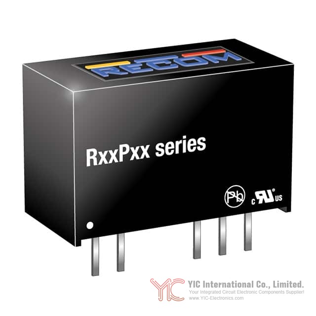
The RxxPxx/R series employs a 7-SIP (Single In-line Package) module format with 4 leads, providing a compact footprint measuring 19.7mm length by 9.8mm width by 12.5mm height. This form factor enables integration into space-constrained applications while maintaining the isolation transformer and power conversion circuitry within a single encapsulated module.
Protection Features and Customization Options in the RxxPxx/R Series
The RxxPxx/R series offers optional continuous short-circuit protection, designated by the /P suffix in the model number. This protection feature limits output current during fault conditions, preventing damage to the converter and downstream circuits when output terminals become shorted.
The continuous short-circuit protection operates by monitoring output current and reducing the output voltage when current exceeds safe limits. This current-limiting behavior protects the converter from thermal runaway while maintaining some level of power delivery to the application. The protection mechanism remains active continuously, distinguishing it from foldback protection schemes that reduce power more aggressively.
The model numbering system for the RxxPxx/R series encodes multiple customization options through suffixes. The isolation rating (/R6.4 or /R8) specifies the reinforced isolation voltage. The pinout option (/X2) provides alternative lead spacing. The protection option (/P) enables continuous short-circuit protection. These options can be combined to create specific variants tailored to application requirements.
For example, the designation R24P05S/R8/P indicates a 24V input, 5V output converter with 8kVDC isolation and continuous short-circuit protection. The R24P05S/R6.4/P/X2 designation specifies the same converter with 6.4kVDC isolation, continuous protection, and alternative pinout. This modular approach to product configuration enables manufacturers to offer variants addressing diverse application needs without requiring entirely separate product lines.
Application Suitability and Selection Considerations for the RxxPxx/R Series
The RxxPxx/R series finds application in environments where reinforced isolation becomes necessary for safety or regulatory compliance. Medical device applications benefit from the IEC/EN60601-1 certification, which validates electrical safety in patient-connected equipment. Laboratory and test equipment applications leverage the IEC/EN61010-1 certification, which addresses the unique transient conditions present in measurement environments.
Industrial applications requiring galvanic isolation between 24V bus systems and low-voltage logic circuits represent another significant use case. The RxxPxx/R series provides the necessary isolation while maintaining compact form factors suitable for distributed power architectures in industrial control systems.
Main Body
Product Overview: RxxPxx/R Series Reinforced Isolation DC/DC Converters
The RxxPxx/R series represents a family of isolated DC/DC converters designed by Recom Power to address the stringent requirements of safety-critical applications. These 1-watt converters deliver a single output of 5V at up to 400mA, operating from input voltage ranges between 21.6V and 26.4V. The fundamental design philosophy centers on providing reinforced galvanic isolation while maintaining compact form factors suitable for modern electronic systems.
The RxxPxx/R series distinguishes itself through a unique reinforced isolation transformer system that achieves isolation ratings of either 6.4kVDC or 8kVDC for one second duration. This architecture enables the converters to meet multiple international safety standards simultaneously, including UL/CSA60950-1, IEC/EN60950-1, UL/ES/CSA60601-1, IEC/EN60601-1, and IEC/EN61010-1 certifications. The breadth of these certifications reflects the converter's suitability across diverse application domains ranging from laboratory equipment to medical devices.
Isolation Architecture and Safety Certification of the RxxPxx/R Series
The reinforced isolation transformer system within the RxxPxx/R series operates as the core safety mechanism, providing galvanic separation between input and output circuits. This isolation prevents fault currents from flowing between different voltage domains, a consideration that becomes paramount in applications where personnel safety or equipment protection depends on electrical separation.
The RxxPxx/R series offers two isolation voltage ratings: 6.4kVDC and 8kVDC, both rated for one-second withstand duration. The selection between these ratings depends on application-specific safety margins and regulatory requirements. For instance, laboratory equipment operating under EN61010-1 standards may require the higher 8kVDC rating to accommodate transient overvoltages that can occur during measurement operations.
The certification portfolio of the RxxPxx/R series reflects its engineered compliance with multiple safety frameworks. UL/CSA60950-1 and IEC/EN60950-1 certifications address general information technology equipment safety, while UL/ES/CSA60601-1 and IEC/EN60601-1 certifications extend applicability to medical device environments where biocompatibility and electrical safety intersect. The IEC/EN61010-1 certification specifically validates the converter's performance in test, measurement, and laboratory equipment contexts where transient conditions and measurement uncertainties present unique challenges.
The RxxPxx/R series has demonstrated qualification with 65kV/μs common-mode transient immunity at 1kV common-mode voltage, indicating robust performance when subjected to rapid voltage changes across the isolation barrier. This specification becomes relevant in applications involving switching power supplies or motor drives where common-mode transients can couple into sensitive circuits.
Input Voltage Range and Output Configuration Options in the RxxPxx/R Series
The RxxPxx/R series accepts input voltages spanning 21.6V to 26.4V, a range that encompasses nominal 24V bus systems commonly found in industrial and telecommunications infrastructure. This input range provides approximately ±10% tolerance around the 24V nominal value, accommodating voltage variations that occur during normal system operation and transient conditions.
The output configuration of the RxxPxx/R series delivers a regulated 5V output at up to 400mA, providing 2 watts of power delivery capability. The output voltage regulation maintains stability across the specified input voltage range and load conditions, enabling reliable operation of downstream digital and analog circuits.
The RxxPxx/R series offers flexibility through alternative pinout configurations designated by the /X2 suffix. This option provides greater than 9mm input/output clearance, accommodating applications where creepage and clearance distances must exceed standard requirements due to pollution degree classifications or dielectric strength specifications. The alternative pinout becomes particularly relevant in high-voltage environments or applications requiring enhanced isolation spacing for regulatory compliance.
Power Delivery Capabilities and Efficiency Performance of the RxxPxx/R Series
The RxxPxx/R series delivers 1 watt of continuous power, with the 5V output capable of supplying 400mA at full load. This power rating establishes the converter as suitable for low-power auxiliary supply applications, gate drive circuits, and sensor interface modules where isolated power distribution becomes necessary.
Efficiency measurements for the RxxPxx/R series, conducted at nominal input voltage and full load with 25°C ambient temperature, reach 80%. This efficiency level reflects the inherent losses within the isolation transformer and power conversion circuitry. The 80% efficiency translates to 0.2 watts of dissipated power at full load, a consideration that influences thermal management strategy and component placement within the application circuit.
The efficiency specification provides a baseline for thermal calculations. When operating at full 400mA output current, the converter dissipates approximately 0.2 watts internally. This dissipation, while modest in absolute terms, becomes significant in thermally constrained environments or when multiple converters operate in close proximity.
Thermal Management and Derating Characteristics of the RxxPxx/R Series
The RxxPxx/R series exhibits thermal derating characteristics that reflect the temperature-dependent performance of the isolation transformer and semiconductor components. Derating curves provided for the RxxPxx/R series indicate maximum ambient temperature limits and corresponding power output reductions at elevated temperatures.
The converter operates across an ambient temperature range from -40°C to +85°C, with full power delivery available at 25°C. As ambient temperature increases beyond 25°C, the maximum available output power decreases according to the derating curve. This derating mechanism protects the isolation transformer from thermal stress while maintaining safety margins for long-term reliability.
For applications operating at elevated ambient temperatures, designers must account for the reduced power availability. For example, an application requiring continuous 400mA output at 60°C ambient temperature would need to verify that the derating curve permits this operating point. If the derating curve indicates reduced current capability at 60°C, the application design must either reduce the load current or implement thermal management measures such as forced-air cooling or heat sinking.
The derating graph for the RxxPxx/R series distinguishes between chamber testing conditions and free-air convection scenarios. Chamber testing represents a controlled laboratory environment, while free-air convection reflects real-world deployment where natural air circulation provides cooling. The free-air convection curve typically shows less aggressive derating than chamber conditions, reflecting the improved heat dissipation available in practical installations.
Electromagnetic Compatibility and Filtering Requirements for the RxxPxx/R Series
The RxxPxx/R series operates within electromagnetic environments defined by EN55032 Class A and Class B standards. Class A environments encompass industrial settings where electromagnetic emissions receive less stringent control, while Class B environments represent commercial and residential installations where stricter emission limits apply.
The RxxPxx/R series datasheet provides EMC filtering suggestions for both Class A and Class B compliance. These filtering networks, implemented on the input and output sides of the converter, attenuate high-frequency switching noise that could otherwise radiate or couple into adjacent circuits.
For Class A applications, the filtering network typically incorporates smaller component values, reflecting the more permissive emission limits. For Class B applications, more aggressive filtering becomes necessary, often requiring larger capacitors and additional ferrite components to achieve compliance. The specific component values depend on the switching frequency of the converter and the impedance characteristics of the application circuit.
Designers implementing the RxxPxx/R series should incorporate the recommended filtering components into their circuit layout, placing them in close proximity to the converter to minimize loop areas and high-frequency coupling paths. The input filter protects the power supply from converter-generated noise, while the output filter prevents converter noise from affecting downstream circuits.
Physical Integration and Pinout Flexibility of the RxxPxx/R Series
The RxxPxx/R series employs a 7-SIP (Single In-line Package) module format with 4 leads, providing a compact footprint measuring 19.7mm length by 9.8mm width by 12.5mm height. This form factor enables integration into space-constrained applications while maintaining the isolation transformer and power conversion circuitry within a single encapsulated module.
The pin connection diagram for the RxxPxx/R series defines the input, output, and ground connections. The standard pinout accommodates typical applications, while the /X2 alternative pinout option provides flexibility for applications requiring modified lead spacing or different physical orientations.
The recommended footprint details provided in the datasheet guide PCB layout design, specifying pad dimensions and spacing that ensure reliable solder connections and mechanical stability. The tolerance specifications (±0.5mm for xx.x dimensions and ±0.25mm for xx.xx dimensions) establish the precision requirements for PCB manufacturing.
Proper PCB layout becomes critical for maintaining the isolation integrity of the RxxPxx/R series. The input and output circuits should be routed on separate PCB layers or with maximum physical separation to prevent capacitive coupling across the isolation barrier. Ground planes should be segmented to prevent return current paths that could compromise isolation effectiveness.
Protection Features and Customization Options in the RxxPxx/R Series
The RxxPxx/R series offers optional continuous short-circuit protection, designated by the /P suffix in the model number. This protection feature limits output current during fault conditions, preventing damage to the converter and downstream circuits when output terminals become shorted.
The continuous short-circuit protection operates by monitoring output current and reducing the output voltage when current exceeds safe limits. This current-limiting behavior protects the converter from thermal runaway while maintaining some level of power delivery to the application. The protection mechanism remains active continuously, distinguishing it from foldback protection schemes that reduce power more aggressively.
The model numbering system for the RxxPxx/R series encodes multiple customization options through suffixes. The isolation rating (/R6.4 or /R8) specifies the reinforced isolation voltage. The pinout option (/X2) provides alternative lead spacing. The protection option (/P) enables continuous short-circuit protection. These options can be combined to create specific variants tailored to application requirements.
For example, the designation R24P05S/R8/P indicates a 24V input, 5V output converter with 8kVDC isolation and continuous short-circuit protection. The R24P05S/R6.4/P/X2 designation specifies the same converter with 6.4kVDC isolation, continuous protection, and alternative pinout. This modular approach to product configuration enables manufacturers to offer variants addressing diverse application needs without requiring entirely separate product lines.
Application Suitability and Selection Considerations for the RxxPxx/R Series
The RxxPxx/R series finds application in environments where reinforced isolation becomes necessary for safety or regulatory compliance. Medical device applications benefit from the IEC/EN60601-1 certification, which validates electrical safety in patient-connected equipment. Laboratory and test equipment applications leverage the IEC/EN61010-1 certification, which addresses the unique transient conditions present in measurement environments.
Industrial applications requiring galvanic isolation between 24V bus systems and low-voltage logic circuits represent another significant use case. The RxxPxx/R series provides the necessary isolation while maintaining compact form factors suitable for distributed power architectures in industrial control systems.
Telecommunications infrastructure applications utilize the RxxPxx/R series for isolated power distribution in equipment racks where multiple voltage domains must remain electrically separated. The 24V input range aligns with standard telecommunications power bus voltages, while the 5V output supplies logic circuits and interface modules.
Selection of the appropriate RxxPxx/R series variant requires consideration of several factors. The isolation voltage rating (6.4kVDC or 8kVDC) depends on the application's safety requirements and regulatory framework. The short-circuit protection option (/P) becomes relevant when the application cannot tolerate converter shutdown during output faults. The alternative pinout option (/X2) addresses creepage and clearance requirements specific to the application's pollution degree classification.
The thermal environment of the application influences whether the standard derating characteristics prove acceptable or whether additional thermal management becomes necessary. Applications operating at elevated ambient temperatures must verify that the derating curve permits the required output current at the expected operating temperature.
The electromagnetic environment determines whether Class A or Class B filtering becomes necessary. Applications in industrial settings may tolerate Class A emissions, while commercial or residential deployments require Class B compliance. The recommended filtering components provided in the datasheet should be incorporated into the circuit design to ensure compliance with the applicable standard.
Conclusion
The RxxPxx/R series represents a comprehensive solution for applications requiring reinforced galvanic isolation combined with compact form factors and multiple safety certifications. The unique reinforced isolation transformer system achieves 6.4kVDC or 8kVDC isolation ratings while maintaining 1-watt power delivery capability. The extensive certification portfolio spanning UL/CSA60950-1, IEC/EN60950-1, medical device standards, and laboratory equipment standards positions the RxxPxx/R series as a versatile choice across diverse application domains.
The modular customization approach through model suffixes enables designers to select specific variants addressing their application's isolation voltage, pinout, and protection requirements. The 80% efficiency and thermal derating characteristics provide the foundation for thermal calculations and power budget planning. The recommended EMC filtering components ensure compliance with EN55032 Class A and Class B standards across the full range of application environments.
Frequently Asked Questions (FAQ)
- Q1. What distinguishes the RxxPxx/R series from standard isolated DC/DC converters?
-
- A1. The RxxPxx/R series employs a unique reinforced isolation transformer system that achieves 6.4kVDC or 8kVDC isolation ratings, exceeding the capabilities of standard converters. This reinforced isolation, combined with multiple international safety certifications including UL/CSA60950-1, IEC/EN60950-1, IEC/EN60601-1, and IEC/EN61010-1, positions the RxxPxx/R series specifically for safety-critical applications where approved or reinforced isolation becomes mandatory.
- Q2. How does the 65kV/μs common-mode transient immunity specification affect application performance?
-
- A2. The 65kV/μs common-mode transient immunity at 1kV common-mode voltage indicates the RxxPxx/R series can withstand rapid voltage changes across the isolation barrier without malfunction. This specification becomes relevant in applications involving switching power supplies or motor drives where common-mode transients can couple into sensitive circuits. Applications with slower transient environments may not require this level of immunity, but applications with fast-switching adjacent circuits benefit from this robust performance.
- Q3. What is the practical significance of the 80% efficiency rating for the RxxPxx/R series?
-
- A3. The 80% efficiency rating means that at full 400mA output current, the converter dissipates approximately 0.2 watts internally. This dissipation influences thermal management strategy and component placement. In thermally constrained environments or when multiple converters operate in close proximity, this 0.2-watt dissipation becomes significant. Designers must account for this heat generation when calculating total system thermal load and determining whether forced-air cooling or heat sinking becomes necessary.
- Q4. How should designers interpret the derating curve for the RxxPxx/R series?
-
- A4. The derating curve indicates that full 400mA output current is available only at 25°C ambient temperature. As ambient temperature increases, the maximum available output current decreases according to the curve. For applications operating at elevated ambient temperatures, designers must verify that the derating curve permits the required output current at the expected operating temperature. If the curve indicates reduced current capability, the application design must either reduce the load current or implement thermal management measures such as forced-air cooling.
- Q5. What is the difference between the /R6.4 and /R8 isolation rating options?
-
- A5. The /R6.4 suffix specifies 6.4kVDC isolation for one second, while the /R8 suffix specifies 8kVDC isolation for one second. The selection between these ratings depends on application-specific safety margins and regulatory requirements. Applications requiring higher safety margins or operating in environments with potential transient overvoltages benefit from the /R8 rating. Applications with less stringent isolation requirements may utilize the /R6.4 rating.
- Q6. When should the /X2 alternative pinout option be selected?
-
- A6. The /X2 option provides greater than 9mm input/output clearance, accommodating applications where creepage and clearance distances must exceed standard requirements. This option becomes relevant in high-voltage environments or applications requiring enhanced isolation spacing for regulatory compliance. Applications with standard creepage and clearance requirements can utilize the standard pinout, while applications with enhanced isolation spacing needs should specify the /X2 option.
- Q7. What does the continuous short-circuit protection (/P option) accomplish?
-
- A7. The continuous short-circuit protection limits output current during fault conditions, preventing damage to the converter and downstream circuits when output terminals become shorted. The protection mechanism monitors output current and reduces the output voltage when current exceeds safe limits. This current-limiting behavior protects the converter from thermal runaway while maintaining some level of power delivery to the application. Applications that cannot tolerate converter shutdown during output faults should specify the /P option.
- Q8. How do the Class A and Class B EMC filtering requirements differ?
-
- A8. Class A environments encompass industrial settings where electromagnetic emissions receive less stringent control, while Class B environments represent commercial and residential installations where stricter emission limits apply. The RxxPxx/R series datasheet provides different filtering component recommendations for each class. Class A filtering typically incorporates smaller component values, while Class B filtering requires more aggressive filtering with larger capacitors and additional ferrite components to achieve compliance.
- Q9. What PCB layout considerations are important for maintaining isolation integrity?
-
- A9. Proper PCB layout becomes critical for maintaining the isolation integrity of the RxxPxx/R series. Input and output circuits should be routed on separate PCB layers or with maximum physical separation to prevent capacitive coupling across the isolation barrier. Ground planes should be segmented to prevent return current paths that could compromise isolation effectiveness. The recommended footprint details provided in the datasheet should guide pad dimensions and spacing to ensure reliable solder connections and mechanical stability.
- Q10. Which applications represent the primary use cases for the RxxPxx/R series?
-
- A10. Medical device applications benefit from the IEC/EN60601-1 certification, which validates electrical safety in patient-connected equipment. Laboratory and test equipment applications leverage the IEC/EN61010-1 certification, which addresses transient conditions in measurement environments. Industrial applications requiring galvanic isolation between 24V bus systems and low-voltage logic circuits represent another significant use case. Telecommunications infrastructure applications utilize the RxxPxx/R series for isolated power distribution in equipment racks where multiple voltage domains must remain electrically separated.
- Q11. How does the 21.6V to 26.4V input voltage range relate to standard power bus systems?
-
- A11. The 21.6V to 26.4V input range encompasses nominal 24V bus systems commonly found in industrial and telecommunications infrastructure. This range provides approximately ±10% tolerance around the 24V nominal value, accommodating voltage variations that occur during normal system operation and transient conditions. Applications utilizing standard 24V power distribution can directly interface with the RxxPxx/R series without additional voltage regulation or conditioning.
- Q12. What thermal management strategies should be considered for applications operating at elevated ambient temperatures?
-
- A12. Applications operating at elevated ambient temperatures must first verify that the derating curve permits the required output current at the expected operating temperature. If the curve indicates reduced current capability, designers can implement thermal management measures such as forced-air cooling, heat sinking, or reduced load current. The derating graph distinguishes between chamber testing conditions and free-air convection scenarios, with free-air convection typically showing less aggressive derating due to improved heat dissipation in practical installations.