Product Overview – KEMET T491B107K010AT
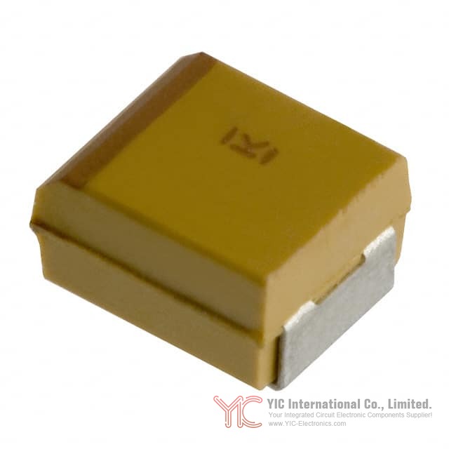
KEMET T491B107K010AT is a molded solid tantalum chip capacitor designed for surface-mount applications. It belongs to the T491 Series of industrial-grade MnO₂ tantalum capacitors and offers a capacitance of 100 µF with a ±10% tolerance at a rated voltage of 10 VDC. The device is housed in the 1411 (3528 metric) case size and has a specified equivalent series resistance (ESR) of 1.2 Ω.
The T491B107K010AT is intended for decoupling and filtering roles in industrial and automotive applications, including DC/DC converters, control units, telecommunications equipment, and portable electronics. It operates over a temperature range from -55°C to +125°C and is moisture sensitivity level (MSL) 1 per J-STD-020, providing unlimited floor life at ≤30°C and 85% RH. When ordered with the appropriate termination, it is RoHS compliant (6/6) according to Directive 2002/95/EC.
2.
Series Technology Background – KEMET T491B107K010AT in the T491 MnO₂ Platform
KEMET T491B107K010AT is part of the T491 Series, an industrial-grade MnO₂ solid tantalum family tailored to modern high-volume SMT assembly. The T491 platform combines established solid tantalum technology with modern materials, process control, and automation to achieve stable performance, reproducibility, and broad applicability in standard electronic assemblies.
Key series-level characteristics that apply to KEMET T491B107K010AT include:
- Compliance with EIA Standard 535BAAC
- MSL 1 classification per J-STD-020, allowing unrestricted floor time under typical assembly environments
- Operating temperature range of -55°C to +125°C
- Available capacitance range across the series from 0.1 µF to 1,000 µF
- Voltage ratings from 2.5 V to 50 V
- Tolerance options of ±10% (K) and ±20% (M)
- Availability in low-profile case sizes and extended value ranges
The series supports multiple termination systems:
- 100% matte tin (Sn) plated terminations (standard “T”), providing good solder wetting and compatibility with lead-free soldering
- Gold-plated terminations (“G”) for conductive epoxy attachment processes
- Tin/lead (SnPb) terminations (“H”, “M”) and non-magnetic variants (“N”, “M” non-magnetic) where legacy solder or magnetic constraints apply
For many case sizes (C, D, E, U, V, X), the series includes 100% surge current testing, which enhances confidence when deploying in power paths subject to inrush conditions.
3.
Electrical Performance and Operating Limits of KEMET T491B107K010AT
KEMET T491B107K010AT has the following primary electrical parameters:
- Capacitance: 100 µF
- Capacitance tolerance: ±10% (designator “K” in the part number)
- Rated voltage: 10 VDC
- ESR: 1.2 Ω (typical value for this 100 µF / 10 V 1411 configuration)
- Technology: Solid tantalum with MnO₂ cathode
- Operating temperature: -55°C to +125°C
As with the broader T491 series, electrical performance varies with frequency, temperature, and applied DC bias. Frequency-dependent behavior includes:
- ESR vs. frequency: Typically, ESR decreases as frequency increases within the capacitor’s effective operating range. For KEMET T491B107K010AT, this trend supports its use in decoupling and output filtering in switching power supplies, where tens to hundreds of kilohertz and beyond are common.
- Capacitance vs. frequency: Effective capacitance tends to decrease at higher frequencies due to dielectric and electrode characteristics. In practical terms, at switching frequencies, the device behaves with somewhat less effective capacitance than the nominal 100 µF measured at low frequency test conditions.
Within the -55°C to +125°C range, the KEMET T491B107K010AT maintains predictable performance, but ripple handling capability is temperature-dependent due to power dissipation limits and ESR variation. The device is designed for DC bias operation up to its rated 10 V when properly derated and used within ripple and temperature specifications.
4.
Voltage Derating and Ripple Handling for KEMET T491B107K010AT
Voltage derating and ripple management are central to reliable use of KEMET T491B107K010AT in power rails and decoupling networks.
Voltage derating for KEMET T491B107K010AT
The T491 series includes recommended voltage derating guidelines to account for real-world conditions such as voltage transients, tolerance stack-up, and temperature-related stress. While the datasheet provides series-level derating tables, the principle is that a margin between the applied DC voltage and the 10 V rated voltage of KEMET T491B107K010AT helps maintain long-term stability and reduces the probability of field failures.
In typical practice, this can mean using KEMET T491B107K010AT on rails where the nominal voltage is below the 10 V rating, factoring in transient peaks and bias variations. For example, using the 10 V device on a nominal 5 V or 6.3 V rail with adequate transient control stays within the intended design window.
Ripple current and ripple voltage constraints for KEMET T491B107K010AT
Permissible ripple is defined by two main criteria:
1. Voltage limit:
- The positive peak of the AC ripple voltage plus any DC bias must not exceed the 10 VDC rating.
- The negative peak combined with any bias must not exceed the reverse voltage limits specified for the series (see Section 5).
2. Power dissipation limit:
- Ripple current flowing through ESR causes internal heating. The maximum power dissipation for the case size, adjusted by temperature compensation multipliers, sets the allowable ripple envelope.
Using the series-level formulation, the allowable rms ripple can be calculated once the maximum power dissipation Pmax and ESR are known:
- Maximum rms ripple current
I(max) = √(Pmax / R)
- Maximum rms ripple voltage
E(max) = Z · √(Pmax / R)
Where:
- I(max) is the rms ripple current
- E(max) is the rms ripple voltage
- Pmax is the maximum power dissipation for the given case size and environment
- R is the ESR at the specified frequency
- Z is the impedance at that frequency
Example use case for KEMET T491B107K010AT:
Consider KEMET T491B107K010AT in the output filter of a 5 V DC/DC buck converter operating at several hundred kilohertz. The engineer must ensure:
- The 5 V DC plus peak ripple never approaches 10 V.
- The ripple current at the switching frequency, when squared and multiplied by ESR (1.2 Ω nominal), remains within Pmax adjusted for the converter’s ambient temperature.
If the ambient temperature is high, derating through the temperature compensation multiplier reduces Pmax, and therefore I(max) and E(max), requiring careful ripple budgeting or parallel capacitors.
5.
Polarity, Reverse Voltage, and Reliability Considerations for KEMET T491B107K010AT
KEMET T491B107K010AT is a polar device and is subject to damage if connected incorrectly. The positive terminal is identified by a stripe marking on the body and, in some cases, a beveled edge.
Reverse voltage behavior for KEMET T491B107K010AT
Solid tantalum capacitors in the T491 series tolerate only a small degree of transient reverse voltage for short durations, as specified in the series reverse voltage table. Continuous reverse operation is not allowed, even if within those transient limits.
For KEMET T491B107K010AT, this implies:
- DC reversed connection on a power rail is not acceptable.
- Transient events that produce momentary small reverse potentials (for example during start-up or from inductive ringing) must be controlled by circuit design to stay within the short-duration limits and avoid continuous reverse bias.
Reliability factors
The T491 series employs 100% surge current testing on specific case sizes (C, D, E, U, V, X). Even where surge testing is not explicitly applied to a particular case, the same industrial-grade MnO₂ technology and process control underpin the KEMET T491B107K010AT. Adhering to the recommended voltage derating, ripple limits, and polarity rules is central to maintaining the expected field reliability.
6.
Mechanical Dimensions and Land Pattern Design for KEMET T491B107K010AT
KEMET T491B107K010AT is a 1411 (3528 metric) chip in the T491 family. The datasheet states that metric dimensions govern, with imperial equivalents in parentheses. The device is molded and features symmetrical, compliant terminations that are optimized for solder joint robustness and automated placement.
For PCB design, the T491 series provides:
- Dimensional outlines for each case size in millimeters (metric governing)
- Notes regarding bevel or notch presence (for some low-profile variants, dimensions B, P, or R may be omitted because these features are absent)
Land pattern (pad) design for KEMET T491B107K010AT
The series includes Table 2 with land dimensions and courtyard recommendations, categorized by density level A, B, and C per IPC-7351 principles:
- Density Level A: For low-density assemblies and wave solder applications, with larger pads and a wider process window.
- Density Level B: For medium density, providing robust solder attachment during reflow.
- Density Level C: For high-density layouts, intended where board real estate is constrained and requiring user qualification according to IPC-7351.
For KEMET T491B107K010AT in 1411 size, selecting the appropriate density level depends on board routing, component spacing, and process capability. For example, in a compact industrial controller PCB with many SMD parts, a density level B or C footprint may be chosen, and the designer would qualify solder joint quality under actual reflow conditions.
7.
Soldering and Assembly Processes for KEMET T491B107K010AT
KEMET T491B107K010AT is compatible with multiple assembly processes shared by the T491 Series:
Supported soldering methods
- Convection reflow
- Infrared reflow
- Vapor phase reflow
- Wave soldering (single or dual wave) for appropriate case sizes; note that tall profiles such as X/7343-43 require attention to wave process setup
Preheating is recommended before soldering to reduce thermal shock and mechanical stress, especially for tantalum chip capacitors.
Reflow profile for KEMET T491B107K010AT
The recommended reflow profile conditions are aligned with IPC/J-STD-020D, the standard used for moisture sensitivity classification. The T491 devices, including KEMET T491B107K010AT, can withstand up to three reflow passes at the specified profile. All temperature references are to the center of the package on the top surface during reflow.
Specific notes include:
- Mild darkening of the gold-colored epoxy during reflow is normal and does not affect performance or marking permanence.
- Care must be taken to respect case-specific limitations (for example, wave soldering with tall cases).
Hand soldering guidelines for KEMET T491B107K010AT
Hand soldering is possible but requires controlled technique:
- Avoid direct contact between the soldering iron tip and the molded case.
- Heat should be applied to the PCB pad, adding solder between pad and termination until proper reflow occurs.
- Wiping the iron along the chip edges or heating the top of the package is not recommended.
These practices help preserve the integrity of the molded body and internal structure of KEMET T491B107K010AT.
8.
Storage, Packaging, and Traceability of KEMET T491B107K010AT
Storage conditions for KEMET T491B107K010AT
The T491 series storage recommendations apply directly to KEMET T491B107K010AT:
- Store in standard working environments.
- Maximum storage temperature: 40°C.
- Maximum storage humidity: 60% RH.
- Avoid large temperature fluctuations to prevent condensation.
- Keep away from atmospheres containing chlorine or sulfur-bearing compounds, which can degrade solderability and materials.
- Use chip stock promptly for optimum solderability, preferably within three years of receipt.
Exposure to high temperature, high humidity, or corrosive atmospheres can degrade solderability and packaging materials (e.g., reel deformation, increased tape peel force).
Tape and reel packaging for KEMET T491B107K010AT
KEMET T491B107K010AT is supplied on 8 mm and 12 mm tape in 7" or 13" reels following EIA-481 “Embossed Carrier Taping of Surface Mount Components for Automatic Handling.” Key aspects include:
- Embossed plastic carrier tape cavities designed to keep components within defined rotation and lateral movement limits.
- Cover tape performance requirements:
- Cover tape break force ≥ 1.0 kg.
- Peel strength within a defined range, with peel angle between 165° and 180° and a peeling speed of 300 ± 10 mm/min.
- Bar code labeling placed on the side of the reel opposite the sprocket holes, following EIA Standards 556 and 624.
Reel dimensions are standardized (see Figure 5 and Table 5 in the T491 documentation). Tape leader and trailer length and maximum camber are also defined to ensure feeder and placement reliability.
Marking and traceability for KEMET T491B107K010AT
The T491 series uses laser-marked case identification. Marking typically includes:
- Capacitance code
- Voltage rating
- Polarity indicator (stripe at positive terminal)
- Date or lot codes (for example, a marking like “230” can represent the 30th week of 2012 according to the example in the series documentation)
This enables traceability for production history and simplifies inspection and verification at incoming quality control and on the assembly line.
9.
Design Support and Simulation Tools for KEMET T491B107K010AT
For KEMET T491B107K010AT and other T491 Series parts, KEMET provides the K-SIM simulation tool accessible at ksim.kemet.com. K-SIM allows detailed analysis of a specific part number’s behavior as a function of:
- Frequency
- Ambient temperature
- DC bias
For KEMET T491B107K010AT, designers can use K-SIM to:
- Evaluate ESR and impedance vs. frequency for a 100 µF / 10 V, 1411 device under specific conditions.
- Estimate effective capacitance at the intended operating frequency.
- Check ripple current and power dissipation in the context of the chosen ambient temperature and voltage stress.
For example, in a telecommunications board with a 5 V rail switching at 300 kHz, K-SIM can be used to verify that a KEMET T491B107K010AT placed near a DC/DC converter output meets ripple and impedance requirements without exceeding the device’s thermal and voltage limits.
10.
Conclusion – Application Positioning of KEMET T491B107K010AT
KEMET T491B107K010AT, a 100 µF, 10 V industrial-grade MnO₂ solid tantalum capacitor in a 1411 (3528 metric) molded chip package, is positioned as a standard solution for decoupling, bulk energy storage, and filtering in surface-mount designs. It fits within the broader T491 Series, which is designed to align with modern automated assembly needs, including reflow compatibility, tape-and-reel packaging, and compliance with MSL 1 requirements.
By combining stable electrical behavior, an extended temperature range, multiple termination options, and detailed guidelines for derating, ripple handling, and soldering, KEMET T491B107K010AT can be integrated into industrial, automotive, portable, and telecom platforms that depend on robust SMT passive components.
Frequently Asked Questions (FAQ)
- Q1. What are the key electrical ratings of KEMET T491B107K010AT?
-
- A1. KEMET T491B107K010AT is rated at 100 µF capacitance with ±10% tolerance, 10 VDC rated voltage, and 1.2 Ω ESR in a 1411 (3528 metric) molded tantalum chip package. It operates from -55°C to +125°C.
- Q2. In which applications can KEMET T491B107K010AT be used effectively?
-
- A2. Typical uses for KEMET T491B107K010AT include decoupling and filtering in industrial and automotive electronics, DC/DC converters, portable devices, telecommunications systems, and control units. Its form factor and SMT compatibility suit dense PCBs where stable bulk capacitance is needed near ICs or power stages.
- Q3. What is the moisture sensitivity level (MSL) of KEMET T491B107K010AT for SMT assembly?
-
- A3. KEMET T491B107K010AT is MSL 1 per J-STD-020, which means it has unlimited floor life when stored at or below 30°C and 85% RH. This simplifies handling and staging on the assembly floor.
- Q4. How should voltage derating be applied to KEMET T491B107K010AT in power rail designs?
-
- A4. The T491 series provides recommended voltage derating guidelines. For KEMET T491B107K010AT, the applied DC voltage plus ripple peaks should be kept below 10 V, with a design margin to account for transients, tolerance, and temperature. Using the 10 V part on typical 5 V or 6.3 V rails is consistent with the derating approach, assuming transient suppression and adherence to ripple and reverse voltage limits.
- Q5. Can KEMET T491B107K010AT tolerate reverse voltage?
-
- A5. KEMET T491B107K010AT, like all T491 solid tantalum capacitors, is polarized. A small transient reverse voltage is permissible for short periods as defined by the series reverse voltage table, but continuous reverse operation is not allowed. The device must be oriented correctly, with the positive terminal identified by the body stripe and, in some cases, a beveled edge.
- Q6. How is ripple current capability determined for KEMET T491B107K010AT?
-
- A6. Ripple capability is set by both voltage and power dissipation limits. For KEMET T491B107K010AT, the total voltage (DC plus AC peaks) must remain below 10 V and within reverse voltage limits. Power dissipation is calculated using P = I²·R, where R is ESR. Maximum allowable rms ripple current is I(max) = √(Pmax / R), and Pmax depends on case size and temperature via a temperature compensation multiplier. These relationships allow designers to size ripple in accordance with thermal capability.
- Q7. Is KEMET T491B107K010AT RoHS compliant?
-
- A7. Yes. When ordered with 100% Sn solder, gold-plated, or non-magnetic 100% Sn terminations, KEMET T491B107K010AT is RoHS Compliant (6/6) in line with Directive 2002/95/EC.
- Q8. What termination finishes are available for the T491 Series and applicable to KEMET T491B107K010AT?
-
- A8. The T491 series supports several termination options, which also apply to KEMET T491B107K010AT depending on the exact part configuration:
- - T: 100% matte tin (Sn) plated
-
- - G: Gold plated
- - H: Standard SnPb solder-coated (SnPb 5% Pb minimum)
-
- - N: Non-magnetic 100% tin (Sn)
- - M: Non-magnetic SnPb
-
- These options support lead-free, conductive epoxy, legacy SnPb, and non-magnetic assembly environments.
- Q9. What are the storage guidelines for KEMET T491B107K010AT before assembly?
-
- A9. KEMET recommends storing KEMET T491B107K010AT at ≤40°C and ≤60% RH, avoiding large temperature changes to prevent condensation and keeping the environment free of chlorine and sulfur-containing compounds. For best solderability, inventory should ideally be used within three years from receipt.
- Q10. Which soldering processes are compatible with KEMET T491B107K010AT?
-
- A10. KEMET T491B107K010AT is compatible with convection reflow, IR reflow, vapor phase reflow, and wave soldering when used in appropriate case sizes and process setups. Preheating is recommended to reduce thermal stress. The component can tolerate up to three reflow passes under IPC/J-STD-020D-profile conditions. Hand soldering is possible but must be done carefully, heating the pad rather than the molded body.
- Q11. How is KEMET T491B107K010AT packaged for automated pick-and-place?
-
- A11. KEMET T491B107K010AT is supplied in embossed plastic carrier tape on 7" and 13" reels according to EIA-481. Carrier tape dimensions, cavity sizes, maximum component rotation and lateral movement, cover tape peel force, and reel geometry are all specified to ensure compatibility with standard tape-fed placement systems.
- Q12. How can the electrical behavior of KEMET T491B107K010AT be simulated before hardware prototyping?
-
- A12. KEMET offers the K-SIM tool at ksim.kemet.com for T491 Series parts, including KEMET T491B107K010AT. K-SIM models frequency-dependent ESR, impedance, capacitance, and the influence of temperature and DC bias, enabling evaluation of decoupling performance, ripple distribution, and stability in the specific environment of the intended circuit.
- Q13. How is polarity and part identification marked on KEMET T491B107K010AT?
-
- A13. KEMET T491B107K010AT uses laser-marked case labeling. Polarity is indicated by a stripe at the positive terminal, and some cases include a beveled edge on the positive side. Markings include codes for capacitance, voltage, and date/lot information, enabling both polarity verification during assembly and traceability for quality control.
- Q14. Are substitutions possible for KEMET T491B107K010AT within the T491 Series?
-
- A14. The series documentation notes that KEMET may substitute higher voltage ratings and tighter tolerance products, including improved ESR, within the same case size at its option. Such substitutions are marked with the higher voltage rating and can offer performance equal to or better than the specified series characteristics, provided they meet the dimensional and functional requirements of the original design.
- Q15. What is the operating temperature range for KEMET T491B107K010AT in automotive or industrial environments?
-
- A15. KEMET T491B107K010AT operates from -55°C to +125°C. This range covers many industrial and automotive under-the-hood and control-unit ambient conditions, subject to proper derating of voltage, ripple, and power dissipation at elevated temperatures.