Product Overview of the KEMET T491 Series
The KEMET T491 represents a mature and widely adopted platform for solid tantalum surface mount capacitors, engineered specifically for automated manufacturing environments. This series combines decades of proven tantalum technology with contemporary materials science and manufacturing processes, resulting in components that meet or exceed EIA standard 535BAAC specifications. The T491 series is classified as moisture sensitivity level (MSL) 1 under J-STD-020, providing unlimited floor life and eliminating the need for bake-out procedures before assembly.
The T491 series addresses the fundamental requirements of modern electronics manufacturing: reliability in high-speed automated placement systems, consistent electrical performance across operating conditions, and compliance with contemporary environmental regulations. These capacitors are manufactured using industrial-grade manganese dioxide (MnO₂) cathode technology, which provides stable performance characteristics and predictable behavior under various electrical and thermal stresses.
Design Architecture and Core Technology of the T491 Series
The T491 series employs solid tantalum technology as its foundational architecture. Unlike electrolytic capacitors that use liquid electrolytes, solid tantalum capacitors utilize a manganese dioxide cathode material that provides several inherent advantages. The MnO₂ cathode creates a stable interface with the tantalum anode, resulting in lower equivalent series resistance (ESR) compared to many alternative technologies and superior frequency response characteristics.
The molded epoxy construction of the T491 series provides mechanical protection and environmental isolation. The epoxy formulation is halogen-free and complies with UL94 V-0 flammability standards, meeting the requirements of modern electronics assembly facilities. The laser-marked case allows for permanent part number identification, ensuring traceability throughout the product lifecycle.
The symmetrical, compliant terminations of the T491 series are designed for compatibility with contemporary solder reflow processes. These terminations provide consistent wetting characteristics and reliable solder joint formation across the full range of reflow parameters. Optional gold-plated terminations are available for applications requiring conductive epoxy attachment processes, offering flexibility for specialized assembly techniques.
Electrical Specifications and Performance Characteristics of the T491 Series
The T491 series delivers predictable electrical performance across its operating range. The fundamental electrical characteristics are defined by the specific part number designation, which encodes capacitance value, tolerance, voltage rating, and termination finish. Understanding these specifications is necessary for proper component selection and circuit design.
The ESR of the T491 series varies with frequency, a characteristic common to all capacitor technologies. At low frequencies, ESR is relatively high, but decreases significantly as frequency increases, reaching minimum values in the kilohertz to low megahertz range. This frequency-dependent behavior reflects the internal construction of the capacitor and the properties of the solid tantalum dielectric.
Capacitance values in the T491 series also exhibit frequency dependence. Measured capacitance typically decreases as frequency increases, a phenomenon related to the dielectric properties of tantalum pentoxide and the internal impedance of the component. This frequency-dependent capacitance must be considered when designing circuits that operate across wide frequency ranges or when precise capacitance values are required at specific frequencies.
Capacitance Range, Tolerance, and Voltage Ratings in the T491 Series
The T491 series provides capacitance values ranging from 0.1 microfarads to 1,000 microfarads, covering the requirements of most decoupling and filtering applications. This broad range allows designers to select appropriate values for specific circuit requirements without requiring multiple component families.
Capacitance tolerance is available in two grades: ±10% and ±20%. The ±10% tolerance grade, designated by the letter "K" in the part number, provides tighter control over actual capacitance values and is recommended for applications where precise capacitance is required. The ±20% tolerance grade, designated by the letter "M", offers cost advantages for applications where wider tolerance is acceptable.
Voltage ratings in the T491 series span from 2.5 volts to 50 volts DC. The specific voltage rating of a component determines the maximum DC bias voltage that can be safely applied. The T491A225K020AG variant discussed in this analysis carries a 20-volt rating, making it suitable for low-voltage applications including portable electronics, telecommunications equipment, and control circuits.
The relationship between voltage rating and physical size follows a consistent pattern across the T491 series. Higher voltage ratings typically require larger case sizes to accommodate the thicker dielectric layer necessary to withstand increased electric field stress. This relationship influences component selection when space constraints are a design consideration.
Frequency Response and Impedance Behavior of the T491 Series
The impedance characteristics of the T491 series vary significantly with frequency, a behavior that directly impacts circuit performance in high-frequency applications. At very low frequencies, impedance is dominated by capacitive reactance, which decreases as frequency increases. However, at higher frequencies, the inductive effects of the component leads and internal construction become significant, causing impedance to increase beyond the theoretical minimum.
The impedance minimum, or resonant frequency, occurs at the point where capacitive reactance equals inductive reactance. For the T491 series, this resonant frequency typically falls in the range of several hundred kilohertz to a few megahertz, depending on the specific case size and capacitance value. Understanding this resonant behavior is important for applications requiring effective filtering or decoupling at specific frequencies.
The ESR characteristics of the T491 series provide insight into power dissipation and filtering effectiveness. Lower ESR values indicate more efficient energy transfer and reduced heat generation under ripple current conditions. The ESR of the T491 series is optimized for typical decoupling and filtering applications, providing a balance between performance and cost.
Thermal Management and Operating Temperature Range of the T491 Series
The T491 series is rated for operation across a temperature range of -55°C to +125°C, encompassing the requirements of industrial and commercial applications. This wide temperature range reflects the stability of solid tantalum technology and the robustness of the MnO₂ cathode material.
Capacitance and ESR both vary with temperature. Capacitance typically decreases at temperature extremes, with the rate of change depending on the specific dielectric formulation. ESR generally increases at lower temperatures and decreases at higher temperatures, a characteristic that must be considered when designing circuits for extreme temperature environments.
The T491 series is rated for 2,000 hours of operation at 125°C, the maximum rated temperature. This lifetime specification indicates the expected operational duration under sustained maximum temperature conditions. For applications operating at lower temperatures, the expected lifetime increases significantly. The relationship between operating temperature and component lifetime follows an exponential curve, with each 10°C reduction in operating temperature approximately doubling the expected lifetime.
Voltage derating is recommended for applications operating at elevated temperatures. As temperature increases, the voltage rating should be reduced to maintain adequate safety margins and ensure reliable long-term operation. KEMET provides specific derating guidelines that account for the combined effects of temperature and voltage stress on component reliability.
Physical Dimensions and Packaging Standards for the T491 Series
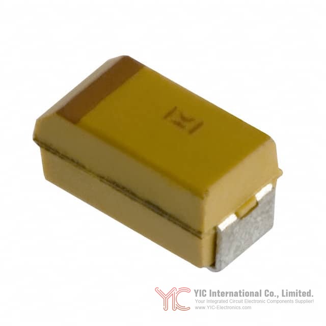
The T491 series employs the 1206 case size, also designated as 3216 in metric notation. This case size measures 3.20 millimeters in length, 1.60 millimeters in width, and 1.80 millimeters in maximum height when seated on a circuit board. These compact dimensions make the T491 series suitable for space-constrained applications while maintaining adequate internal volume for reliable component construction.
The 1206 case size represents a balance between component density and manufacturing ease. It is large enough to accommodate the internal construction necessary for reliable performance, yet small enough to enable high-density circuit board layouts. This size is widely supported by automated assembly equipment, ensuring compatibility with contemporary manufacturing processes.
The physical construction includes a molded epoxy body with symmetrical terminations on the two ends. The terminations are designed to provide reliable solder joints when processed through standard reflow soldering equipment. The laser-marked case includes the manufacturer designation, capacitance value, voltage rating, and date code, enabling complete traceability and verification of component specifications.
Surface Mount Compatibility and Land Pattern Design for the T491 Series
The T491 series is optimized for surface mount assembly using automated pick-and-place equipment. The component geometry and termination design ensure reliable placement and consistent solder joint formation across the full range of reflow parameters.
Land pattern design for the T491 series follows IPC standard 7351 guidelines, with three density levels available to accommodate different circuit board layout requirements. Density Level A provides the widest process window and is recommended for applications with lower component density or where wave soldering is employed. Density Level B offers a balance between component density and process robustness, suitable for most contemporary applications. Density Level C enables maximum component density for high-density applications but requires careful process validation to ensure reliable solder joint formation.
The land pattern dimensions account for the component size, solder paste volume requirements, and the thermal characteristics of the reflow process. Proper land pattern design is essential for achieving consistent solder joint quality and preventing solder bridges or insufficient solder connections.
Termination Options and Soldering Compatibility of the T491 Series
The T491 series offers multiple termination finish options to accommodate different assembly processes and application requirements. The standard termination is 100% matte tin (Sn) plating, which provides excellent wetting characteristics and compatibility with lead-free solder systems. This termination option is RoHS compliant and meets the requirements of contemporary environmental regulations.
Gold-plated terminations are available for applications requiring conductive epoxy attachment processes. The gold plating provides a stable, non-oxidizing surface that ensures reliable electrical contact when using conductive adhesives instead of solder. This option is particularly useful for applications where thermal stress from reflow soldering must be minimized.
Tin/lead (Sn/Pb) terminations are available upon request for applications requiring compatibility with traditional lead-containing solder systems. While less common in contemporary applications due to environmental regulations, this option remains available for legacy systems or specialized applications where lead-free solder is not suitable.
The T491 series is compatible with wave soldering, convection reflow, infrared reflow, and vapor phase reflow processes. Preheating is recommended to minimize thermal stress during the reflow process. The components can safely withstand a maximum of three reflow passes at standard IPC/J-STD-020D conditions, providing flexibility for rework and repair operations.
Hand soldering should be performed with care due to the difficulty in process control. The soldering iron should be used to heat the solder pad, with solder applied between the pad and the termination until reflow occurs. The iron should be removed immediately after reflow to avoid thermal damage to the molded epoxy case. Wiping the edges of the component or heating the top surface is not recommended.
Environmental Compliance and Regulatory Standards for the T491 Series
The T491 series meets RoHS Directive 2002/95/EC requirements when ordered with 100% tin solder, gold-plated, or non-magnetic 100% tin terminations. The halogen-free epoxy formulation complies with UL94 V-0 flammability standards and meets outgassing requirements under ASTM E-595 testing.
The REACH regulation status indicates that the T491 series is unaffected by REACH requirements, simplifying compliance documentation for applications in European markets. The RoHS3 compliance status confirms that the component meets the most current version of the RoHS directive, including restrictions on phthalates and other regulated substances.
The ECCN classification of EAR99 indicates that the T491 series is not subject to export control restrictions, enabling unrestricted distribution to authorized customers worldwide. The HTSUS code 8532.21.0050 provides the appropriate tariff classification for customs purposes.
Ripple Current and Power Dissipation Considerations for the T491 Series
Ripple current and ripple voltage are related to the ESR and power dissipation capabilities of the T491 series. The maximum permissible AC ripple voltage is limited by two criteria: the positive peak AC voltage plus any DC bias voltage must not exceed the DC voltage rating, and the negative peak AC voltage in combination with bias voltage must not exceed the allowable reverse voltage limits.
The maximum power dissipation capability of the T491 series varies by case size. For the 1206 case size, the maximum power dissipation is determined by the thermal characteristics of the component and the ability of the circuit board to dissipate heat. This maximum power dissipation rating must be reduced at elevated operating temperatures according to specific temperature compensation multipliers provided in the technical documentation.
The maximum allowable RMS ripple current can be calculated using the formula: I(max) = √(P max / R), where P max is the maximum power dissipation in watts and R is the ESR in ohms at the specified frequency. Similarly, the maximum allowable RMS ripple voltage can be calculated using: E(max) = Z × √(P max / R), where Z is the impedance in ohms at the specified frequency.
For example, if a T491 component has a maximum power dissipation of 0.5 watts and an ESR of 60 ohms at 100 kilohertz, the maximum allowable RMS ripple current would be approximately 91 milliamps. This calculation enables designers to verify that the ripple current in their application does not exceed the component's capabilities.
Reverse Voltage Protection and Polarity Requirements of the T491 Series
Solid tantalum capacitors are polar devices and must be connected with correct polarity to ensure reliable operation. The positive terminal is identified on the component body by a stripe or, in some cases, a beveled edge. Connecting the component with reversed polarity can result in permanent damage or catastrophic failure.
A small degree of transient reverse voltage is permissible for short periods, with specific limits defined in the technical documentation. However, the T491 series should not be operated continuously in reverse mode, even within these transient limits. Circuit designs must include protection against reverse voltage conditions, either through careful circuit topology or through the use of protective components such as diodes.
The reverse voltage limits vary by voltage rating and case size. For the 20-volt rated T491A225K020AG variant, the specific reverse voltage limits are defined in the component's detailed specifications. Designers must verify that their circuit topology cannot inadvertently apply reverse voltage to the capacitor under any operating condition, including fault conditions or transient events.
Storage, Handling, and Shelf Life Management for the T491 Series
The T491 series should be stored in normal working environments to maintain solderability and component reliability. KEMET recommends that maximum storage temperature not exceed 40°C and maximum storage humidity not exceed 60% relative humidity. Temperature fluctuations should be minimized to avoid condensation on the components, and storage atmospheres should be free of chlorine and sulfur-bearing compounds.
The shelf life of the T491 series is optimized when components are used promptly after receipt, preferably within three years. Extended storage beyond this period may result in degraded solderability due to oxidation of the termination surfaces. However, the components themselves remain robust and functional even after extended storage if proper environmental conditions are maintained.
Packaging materials can be degraded by high temperature and humidity. Plastic reels may soften or warp, and tape peel force may increase, potentially affecting automated assembly equipment compatibility. Proper storage conditions protect both the components and the packaging materials, ensuring reliable performance throughout the product lifecycle.
Conclusion
The KEMET T491 series represents a mature, reliable platform for solid tantalum surface mount capacitors, engineered for automated manufacturing and designed to meet the demanding requirements of contemporary electronics applications. The combination of proven tantalum technology, optimized MnO₂ cathode construction, and compliance with current environmental standards makes the T491 series a dependable choice for decoupling, filtering, and energy storage applications across industrial, commercial, and consumer electronics markets. The comprehensive range of capacitance values, voltage ratings, and termination options enables designers to select appropriate components for virtually any application requirement, while the wide operating temperature range and extended lifetime at rated conditions ensure reliable long-term performance in diverse operating environments.
Frequently Asked Questions (FAQ)
- Q1. What is the difference between the ±10% and ±20% tolerance grades available in the T491 series, and how should I choose between them?
-
- A1. The T491 series offers two tolerance grades: ±10% (designated "K" in the part number) and ±20% (designated "M"). The ±10% grade provides tighter control over actual capacitance values and is recommended for applications where precise capacitance is required for proper circuit operation, such as timing circuits or precision filters. The ±20% grade offers cost advantages and is suitable for applications where wider tolerance is acceptable, such as general-purpose decoupling applications. Selection depends on your circuit's sensitivity to capacitance variation and your cost requirements.
- Q2. Can the T491 series be used in applications requiring reverse voltage protection, and what are the limits?
-
- A2. The T491 series is a polar device and should not be operated continuously in reverse polarity. However, a small degree of transient reverse voltage is permissible for short periods, with specific limits defined in the technical documentation based on voltage rating and case size. For the T491A225K020AG variant, these limits are specified in the detailed ratings. Circuit designs should include protection against reverse voltage through careful topology design or protective components such as diodes to prevent accidental polarity reversal.
- Q3. How does temperature affect the performance of the T491 series, and what derating should be applied for elevated temperature operation?
-
- A3. The T491 series is rated for operation from -55°C to +125°C. Both capacitance and ESR vary with temperature: capacitance typically decreases at temperature extremes, while ESR generally increases at lower temperatures and decreases at higher temperatures. For applications operating at elevated temperatures, voltage derating is recommended to maintain adequate safety margins. KEMET provides specific derating guidelines that account for the combined effects of temperature and voltage stress. The component lifetime approximately doubles for each 10°C reduction in operating temperature below the maximum rated temperature.
- Q4. What is the maximum ripple current that the T491 series can handle, and how is this calculated?
-
- A4. The maximum permissible ripple current depends on the component's ESR, power dissipation capability, and operating temperature. The maximum allowable RMS ripple current is calculated using the formula: I(max) = √(P max / R), where P max is the maximum power dissipation in watts and R is the ESR in ohms at the specified frequency. The maximum power dissipation rating must be reduced at elevated operating temperatures according to temperature compensation multipliers. Designers should verify that their application's ripple current does not exceed the calculated maximum to ensure reliable operation and prevent thermal damage.
- Q5. Are the T491 series components compatible with lead-free solder processes, and what termination options are available?
-
- A5. Yes, the T491 series is fully compatible with lead-free solder processes. The standard termination is 100% matte tin (Sn) plating, which provides excellent wetting characteristics and compatibility with lead-free solder systems. This termination is RoHS compliant and meets contemporary environmental regulations. Gold-plated terminations are available for applications requiring conductive epoxy attachment processes. Tin/lead (Sn/Pb) terminations are available upon request for legacy applications. The components can safely withstand a maximum of three reflow passes at standard IPC/J-STD-020D conditions.
- Q6. What storage conditions are recommended for the T491 series to maintain solderability and component reliability?
-
- A6. The T491 series should be stored in normal working environments with maximum storage temperature not exceeding 40°C and maximum storage humidity not exceeding 60% relative humidity. Temperature fluctuations should be minimized to avoid condensation, and storage atmospheres should be free of chlorine and sulfur-bearing compounds. For optimized solderability, components should be used promptly after receipt, preferably within three years. Extended storage beyond this period may result in degraded solderability due to oxidation of termination surfaces, though the components themselves remain functional if proper environmental conditions are maintained.
- Q7. How does frequency affect the capacitance and ESR of the T491 series, and why is this important for circuit design?
-
- A7. Both capacitance and ESR in the T491 series exhibit frequency dependence. Capacitance typically decreases as frequency increases due to the dielectric properties of tantalum pentoxide and internal impedance effects. ESR decreases as frequency increases from DC to the kilohertz range, reaching minimum values in the low megahertz range, then increases at higher frequencies due to inductive effects. This frequency-dependent behavior is important for circuit design because it affects the component's filtering effectiveness and impedance characteristics at different frequencies. Designers must consider these frequency effects when selecting components for applications operating across wide frequency ranges or when precise performance at specific frequencies is required.
- Q8. What is the moisture sensitivity level (MSL) of the T491 series, and what does this mean for handling and assembly?
-
- A8. The T491 series is classified as MSL 1 under J-STD-020, which means it has unlimited floor life and does not require bake-out procedures before assembly. This classification indicates that the component can be stored and handled in normal manufacturing environments without special moisture control measures. Unlike higher MSL components that require controlled humidity storage and bake-out procedures before reflow soldering, the T491 series simplifies manufacturing logistics and reduces assembly costs by eliminating these special handling requirements.
- Q9. What are the physical dimensions of the T491 series 1206 case size, and how does this compare to other case sizes?
-
- A9. The T491 series 1206 case size measures 3.20 millimeters in length, 1.60 millimeters in width, and 1.80 millimeters in maximum height when seated on a circuit board. This case size represents a balance between component density and manufacturing ease. It is large enough to accommodate the internal construction necessary for reliable performance, yet small enough to enable high-density circuit board layouts. The 1206 size is widely supported by automated assembly equipment, ensuring compatibility with contemporary manufacturing processes. This size is suitable for most decoupling and filtering applications where space constraints are moderate.
- Q10. How should hand soldering be performed on the T491 series components, and what precautions should be taken?
-
- A10. Hand soldering should be performed with care due to the difficulty in process control. The soldering iron should be used to heat the solder pad, with solder applied between the pad and the termination until reflow occurs. The iron should be removed immediately after reflow to avoid thermal damage to the molded epoxy case. Wiping the edges of the component or heating the top surface is not recommended, as these techniques can damage the component or create unreliable solder joints. If hand soldering is necessary, it should be performed by experienced technicians who understand the thermal requirements and limitations of solid tantalum capacitors.
- Q11. What environmental compliance standards does the T491 series meet, and what does this mean for regulatory requirements?
-
- A11. The T491 series meets RoHS Directive 2002/95/EC requirements when ordered with 100% tin solder, gold-plated, or non-magnetic 100% tin terminations. The halogen-free epoxy formulation complies with UL94 V-0 flammability standards and meets outgassing requirements under ASTM E-595 testing. The REACH regulation status indicates that the T491 series is unaffected by REACH requirements, simplifying compliance documentation for European markets. The RoHS3 compliance status confirms compliance with the most current version of the RoHS directive. These certifications enable the T491 series to be used in applications subject to environmental regulations in Europe and other regions with similar requirements.
- Q12. What is the relationship between case size and voltage rating in the T491 series, and how does this affect component selection?
-
- A12. The relationship between voltage rating and physical size follows a consistent pattern across the T491 series: higher voltage ratings typically require larger case sizes to accommodate the thicker dielectric layer necessary to withstand increased electric field stress. This relationship influences component selection when space constraints are a design consideration. If your circuit board layout has limited space, you may need to select a lower voltage rating component that fits the available space, or alternatively, you may need to increase board space to accommodate a higher voltage rating component if your application requires it. Understanding this relationship helps optimize the balance between performance requirements and physical constraints.