Product Overview of the NC7SZ125 Buffer
The NC7SZ125 is a single-element buffer with three-state output capability, manufactured by onsemi using advanced CMOS technology. This device belongs to the Ultra-High Speed (UHS) TinyLogic family and is engineered to deliver rapid signal propagation while maintaining minimal static power consumption across a broad supply voltage range. The NC7SZ125 operates reliably from 1.65 V to 5.5 V, making it suitable for diverse voltage domain applications including legacy 5 V systems and modern 3.3 V digital circuits.
The device addresses a fundamental requirement in digital systems: the need to buffer and control signal distribution across multiple circuit nodes. By providing high-impedance inputs and outputs during power-down conditions, the NC7SZ125 enables efficient power management in battery-powered and always-on systems. The three-state output architecture allows multiple devices to share a common bus without contention, a configuration widely used in microprocessor systems, memory interfaces, and industrial control applications.
Architecture and Operating Principles of the NC7SZ125
The NC7SZ125 implements a straightforward yet effective architecture consisting of a single buffer stage with integrated three-state output control. The device contains two primary control inputs: the data input (A) and the output enable input (OE). When OE is held at logic low, the buffer actively drives the output (Y) to reflect the state of input A. When OE transitions to logic high, the output enters a high-impedance state, effectively disconnecting the device from the output bus.
This architecture enables practical implementation of bus-sharing scenarios. Consider a system where multiple processors need to communicate over a shared data bus. Each processor connects its data through an NC7SZ125 buffer, with the OE pin controlled by bus arbitration logic. Only one processor's buffer drives the bus at any given time, while all others maintain high impedance, preventing electrical conflicts and data corruption.
The internal CMOS design provides symmetric rise and fall time characteristics, ensuring predictable signal transitions. The device maintains high input impedance above ground when supply voltage is absent, and the inputs tolerate voltages up to 5.5 V regardless of the operating supply voltage. This over-voltage tolerance facilitates direct interfacing between different voltage domains without additional level-shifting circuitry.
Electrical Performance Characteristics of the NC7SZ125
The NC7SZ125 delivers propagation delays as low as 2.1 nanoseconds at 5.0 V supply voltage with a 50 pF load, enabling its use in time-critical applications. At 3.3 V operation, typical propagation delay measures 2.5 nanoseconds, matching the performance of legacy LCX-series devices while consuming significantly less power. These timing specifications apply to both low-to-high (tPLH) and high-to-low (tPHL) transitions, providing symmetric switching behavior.
Output drive capability reaches ±24 mA at 3.0 V supply voltage and ±32 mA at 4.5 V, allowing the device to drive moderate capacitive loads and multiple logic inputs without external buffering. The high output drive current enables direct connection to transmission lines and backplane traces in industrial applications, reducing the need for additional driver stages.
Input and output voltage thresholds scale with supply voltage, maintaining consistent noise margins across the operating range. At 1.65 V supply, the high-level input threshold (VIH) is 0.65 × VCC, while the low-level threshold (VIL) is 0.35 × VCC. At higher supply voltages between 2.30 V and 5.50 V, VIH increases to 0.70 × VCC and VIL decreases to 0.30 × VCC, providing improved noise immunity in systems operating at elevated voltages.
Power Supply and Thermal Management of the NC7SZ125
The NC7SZ125 operates across a supply voltage range from 1.65 V to 5.50 V during normal operation, with data retention capability down to 1.50 V. This broad operating range accommodates systems transitioning between different power states or incorporating multiple voltage domains. The device maintains functionality across the industrial temperature range of -40°C to +85°C, suitable for automotive, industrial, and telecommunications applications.
Quiescent supply current remains exceptionally low at 2 microamperes typical and 20 microamperes maximum when inputs are held at 5.5 V and the device is in standby. This minimal static consumption makes the NC7SZ125 suitable for battery-powered applications where extended operating life is required. When the output is in the three-state condition, leakage current through the output stage remains below ±10 microamperes across the full voltage range, preventing unwanted current paths through pull-up or pull-down resistors on shared buses.
Thermal resistance varies by package type. The SC-74A and SOT23-5 packages exhibit thermal resistance of 320°C/W, while the SC-88A package provides 377°C/W. The MicroPak and MicroPak2 packages offer superior thermal performance at 154°C/W, enabling higher power dissipation in compact form factors. Maximum power dissipation in still air ranges from 332 mW for the SC-88A package to 812 mW for the MicroPak variants, providing adequate thermal headroom for continuous operation in typical applications.
Input and Output Specifications of the NC7SZ125
The NC7SZ125 accepts input signals ranging from 0 V to 5.5 V, independent of the supply voltage. This over-voltage tolerance eliminates the need for external clamping diodes when interfacing with higher voltage domains. Input leakage current remains below ±10 microamperes across the full voltage range, minimizing loading on preceding logic stages and reducing power consumption in systems with many interconnected devices.
Output voltage levels depend on both the supply voltage and the output current. At 1.65 V supply with 100 microamperes of output current, the high-level output voltage (VOH) reaches 1.55 V minimum, while the low-level output voltage (VOL) remains at 0.10 V maximum. At higher supply voltages and currents, output voltage swings approach the supply rails. For example, at 4.5 V supply with 32 milliamperes of output current, VOH reaches 3.80 V minimum and VOL remains below 0.55 V maximum.
The output tolerates voltages above VCC when in the three-state condition, allowing external pull-up resistors to establish bus voltage levels higher than the supply voltage. This capability is particularly useful in open-drain bus architectures where multiple devices share a common pull-up resistor to a higher voltage rail.
Three-State Output Control and Logic Functionality of the NC7SZ125
The three-state output control mechanism provides the foundation for bus-sharing applications. The function table defines four operational states: when OE is low and input A is low, the output drives low; when OE is low and input A is high, the output drives high; when OE is high regardless of input state, the output enters high impedance. This simple logic enables straightforward implementation of multiplexing and bus arbitration circuits.
Output enable time (tPZL and tPZH) measures the delay from OE transition to the output reaching high impedance. At 3.3 V supply with 50 pF load and 500 ohm pull-up resistor, typical output enable time is 6.2 nanoseconds, allowing rapid bus release when multiple devices contend for the same line. Output disable time (tPLZ and tPHZ) measures the delay from OE transition to the output actively driving. Typical disable time at 3.3 V is 5.7 nanoseconds, enabling quick bus acquisition when arbitration logic grants access.
In practical applications, these timing specifications prevent bus contention during transitions. Consider a system where processor A releases the bus by setting its OE high, and processor B acquires the bus by setting its OE low. The NC7SZ125 timing ensures that processor A's output reaches high impedance before processor B begins driving, preventing momentary short circuits that could damage the devices or corrupt data.
Package Options and Physical Integration of the NC7SZ125
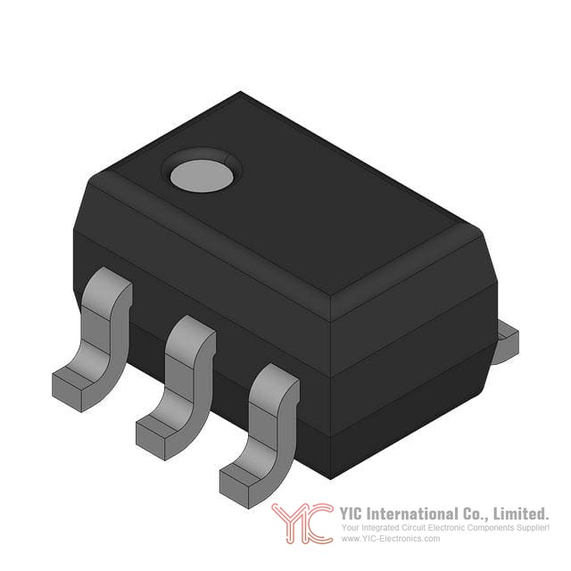
The NC7SZ125 is available in four distinct package options, each optimized for different application requirements. The SC-74A package (CASE 318BQ) measures 3.00 × 1.50 × 0.95 millimeters with 0.95 millimeter lead pitch, providing a compact footprint suitable for space-constrained applications. The SOT23-5 package offers similar dimensions and is widely supported by assembly equipment worldwide.
The SC-88A package (CASE 419A-02) provides an alternative form factor with slightly different thermal characteristics. The MicroPak package (CASE 517DP) delivers the smallest footprint with superior thermal performance, making it ideal for high-density applications where thermal management is critical. The MicroPak2 variant offers equivalent electrical performance with alternative mechanical specifications.
All packages employ surface-mount technology with standardized lead finishes compatible with lead-free soldering processes. Pin configurations remain consistent across packages, with the data input (A) on pin 2, output enable (OE) on pin 1, ground on pin 3, output (Y) on pin 4, and supply voltage (VCC) on pin 5 or 6 depending on package type. The MicroPak package includes a no-connect pin (NC) to maintain consistent pin numbering.
Environmental Compliance and Reliability of the NC7SZ125
The NC7SZ125 meets RoHS3 compliance requirements, containing no lead or other restricted substances. The device exhibits moisture sensitivity level (MSL) 1, indicating unlimited shelf life without special storage conditions. This environmental compliance simplifies procurement and supply chain management while meeting regulatory requirements in consumer electronics, automotive, and industrial markets.
Electrostatic discharge (ESD) protection reaches 4000 volts using the human body model (JEDEC JESD22-A114) and 2000 volts using the charge device model (JEDEC JESD22-C101). These protection levels provide robust immunity to static discharge events during handling and assembly, reducing field failures and warranty costs.
The device operates reliably across the full industrial temperature range from -40°C to +85°C, with absolute maximum ratings extending to -65°C storage temperature and +150°C junction temperature under bias. Lead temperature during soldering reaches +260°C for 10 seconds, compatible with standard reflow soldering processes used in modern electronics manufacturing.
Conclusion
The NC7SZ125 represents a mature, highly optimized solution for buffering and three-state output control in digital systems. Its combination of ultra-high speed operation, broad supply voltage range, low power consumption, and compact packaging makes it suitable for applications ranging from legacy 5 V systems to modern 3.3 V digital circuits. The device's over-voltage tolerance on inputs and outputs simplifies multi-voltage domain integration, while its three-state output architecture enables efficient bus-sharing implementations. With multiple package options providing different thermal and footprint characteristics, the NC7SZ125 accommodates diverse physical integration requirements. Environmental compliance and robust ESD protection ensure reliable long-term operation in demanding applications.
Frequently Asked Questions (FAQ)
- Q1. What is the primary function of the NC7SZ125, and in what types of applications is it typically used?
-
- A1. The NC7SZ125 is a single-element buffer with three-state output control. It is primarily used in applications requiring signal buffering and bus arbitration, such as microprocessor systems with shared data buses, memory interfaces, industrial control systems, and telecommunications equipment. The three-state output allows multiple devices to share a common bus without electrical contention.
- Q2. What supply voltage range does the NC7SZ125 support, and how does this affect device selection?
-
- A2. The NC7SZ125 operates from 1.65 V to 5.5 V during normal operation, with data retention capability down to 1.50 V. This broad range accommodates both legacy 5 V systems and modern 3.3 V digital circuits, as well as systems with multiple voltage domains. When selecting the device, verify that your system's supply voltage falls within this range and consider the propagation delay specifications at your specific operating voltage, as timing performance varies with supply voltage.
- Q3. How fast is the NC7SZ125, and what does propagation delay mean in practical terms?
-
- A3. The NC7SZ125 achieves propagation delays as low as 2.1 nanoseconds at 5.0 V supply with a 50 pF load. Propagation delay is the time required for a change at the input to appear at the output. In practical terms, this means the device can respond to input changes in approximately 2-6 nanoseconds depending on supply voltage and load conditions. This speed makes the NC7SZ125 suitable for time-critical applications including high-speed data buses and real-time control systems.
- Q4. What does "three-state output" mean, and why is this feature important?
-
- A4. Three-state output means the output can exist in three conditions: logic high, logic low, or high impedance (disconnected). The output enable (OE) pin controls this behavior. When OE is low, the output actively drives high or low based on the input. When OE is high, the output enters high impedance, effectively disconnecting from the bus. This feature is important because it allows multiple devices to share a single bus line without creating electrical conflicts. Only one device drives the bus at a time while others remain disconnected.
- Q5. Can the NC7SZ125 interface between different voltage domains, such as 5 V and 3.3 V systems?
-
- A5. Yes, the NC7SZ125 facilitates voltage domain translation through its over-voltage tolerance. The inputs tolerate voltages up to 5.5 V independent of the supply voltage, and the output tolerates voltages above VCC when in the three-state condition. This means a 3.3 V powered NC7SZ125 can accept 5 V input signals without damage, and its output can be pulled to 5 V through an external resistor when in the three-state condition. However, for active driving from 3.3 V to 5 V, additional level-shifting circuitry may be required depending on the receiving device's input thresholds.
- Q6. What is the output drive capability of the NC7SZ125, and how does this affect load selection?
-
- A6. The NC7SZ125 provides output drive capability of ±24 mA at 3.0 V supply and ±32 mA at 4.5 V supply. This drive current allows the device to directly drive moderate capacitive loads and multiple logic inputs without external buffering. For example, at 3.3 V operation, the device can drive approximately 10-15 standard TTL inputs or charge a 50 pF load in approximately 5 nanoseconds. When selecting loads, ensure the total current demand does not exceed the specified output current limits to maintain proper output voltage levels and prevent device damage.
- Q7. What are the power consumption characteristics of the NC7SZ125, and is it suitable for battery-powered applications?
-
- A7. The NC7SZ125 exhibits exceptionally low quiescent supply current of 2 microamperes typical and 20 microamperes maximum in standby conditions. When the output is in the three-state condition, leakage current remains below ±10 microamperes. These characteristics make the device suitable for battery-powered applications where extended operating life is required. The low static power consumption means the device contributes minimally to overall system power budget, particularly in applications where the device spends significant time in standby or three-state conditions.
- Q8. What package options are available for the NC7SZ125, and how do they differ?
-
- A8. The NC7SZ125 is available in four packages: SC-74A (3.00 × 1.50 × 0.95 mm), SOT23-5 (similar dimensions), SC-88A, and MicroPak (smallest footprint with superior thermal performance). The SC-74A and SOT23-5 packages provide thermal resistance of 320°C/W, while the SC-88A offers 377°C/W. The MicroPak packages deliver the best thermal performance at 154°C/W, enabling higher power dissipation in compact form factors. Selection depends on space constraints, thermal requirements, and assembly equipment compatibility.
- Q9. What are the input voltage thresholds for the NC7SZ125, and how do they vary with supply voltage?
-
- A9. Input voltage thresholds scale with supply voltage to maintain consistent noise margins. At 1.65 V supply, the high-level input threshold (VIH) is 0.65 × VCC and the low-level threshold (VIL) is 0.35 × VCC. At supply voltages between 2.30 V and 5.50 V, VIH increases to 0.70 × VCC and VIL decreases to 0.30 × VCC. This scaling ensures that the device maintains adequate noise immunity across the entire operating voltage range. When designing circuits, ensure input signals exceed VIH for reliable high detection and remain below VIL for reliable low detection.
- Q10. What is the operating temperature range of the NC7SZ125, and what applications does this support?
-
- A10. The NC7SZ125 operates reliably from -40°C to +85°C, covering the industrial temperature range. This range supports applications in automotive systems (engine control, body electronics), industrial equipment (process control, factory automation), telecommunications infrastructure, and outdoor installations. The device maintains specified electrical characteristics across this entire range, though propagation delay and power consumption may vary slightly at temperature extremes. For applications requiring extended temperature ranges, verify that your specific system requirements fall within these limits.
- Q11. How does the NC7SZ125 handle unused inputs, and what precautions should be taken?
-
- A11. Unused inputs must be held at either logic high or logic low; they cannot be left floating. Floating inputs can cause unpredictable behavior, increased power consumption, and potential oscillation. In practical implementation, unused inputs should be connected to either VCC (for high) or GND (for low) through appropriate resistors or direct connections. If the input is not used in the application logic, connecting it to the appropriate rail ensures stable, predictable device operation and prevents noise-induced switching.
- Q12. What ESD protection does the NC7SZ125 provide, and is additional protection needed?
-
- A12. The NC7SZ125 provides 4000 volts of ESD protection using the human body model and 2000 volts using the charge device model. These protection levels provide robust immunity to static discharge events during handling and assembly. However, in applications with particularly harsh electrostatic environments or where the device is exposed to direct human contact, additional system-level ESD protection may be beneficial. This could include external transient suppression diodes or ferrite beads on signal lines, depending on the specific application requirements.
- Q13. What is the relationship between output current and output voltage in the NC7SZ125?
-
- A13. Output voltage levels depend on both the supply voltage and the output current. As output current increases, the output voltage deviates further from the ideal rail voltage due to internal resistance. For example, at 1.65 V supply with 100 microamperes output current, VOH is 1.55 V, but at 4 milliamperes it drops to 1.29 V. Similarly, VOL increases from 0.10 V at 100 microamperes to 0.24 V at 4 milliamperes. When designing circuits, account for these voltage deviations when calculating noise margins and ensuring proper logic level detection by receiving devices.
- Q14. How do the output enable and disable times affect bus arbitration in multi-master systems?
-
- A14. Output enable time (tPZL/tPZH) is the delay from OE transition to high impedance, while output disable time (tPLZ/tPHZ) is the delay from OE transition to active driving. In multi-master bus systems, these timings prevent contention. When one master releases the bus (OE high), its output reaches high impedance within approximately 6 nanoseconds at 3.3 V. When another master acquires the bus (OE low), it begins driving within approximately 5.7 nanoseconds. Bus arbitration logic must account for these delays to ensure one master fully releases before another begins driving, preventing momentary short circuits.
- Q15. What environmental compliance certifications does the NC7SZ125 hold, and what does this mean for procurement?
-
- A15. The NC7SZ125 meets RoHS3 compliance, containing no lead or other restricted substances, and exhibits moisture sensitivity level (MSL) 1, indicating unlimited shelf life without special storage conditions. These certifications simplify procurement and supply chain management by eliminating special handling requirements and meeting regulatory requirements in consumer electronics, automotive, and industrial markets. The device can be stored at room temperature without desiccant packaging, reducing logistics costs and complexity compared to more sensitive components.