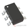
Product Overview of the AD7414/AD7415 Series
The AD7414/AD7415 series represents a complete digital temperature monitoring solution manufactured by Analog Devices Inc., designed for applications requiring accurate thermal measurement and management. These devices integrate a precision temperature sensor with a 10-bit analog-to-digital converter within compact 5-lead and 6-lead SOT-23 packages, making them suitable for space-constrained applications across consumer electronics, computing systems, and industrial equipment.
The AD7414 variant includes six leads and provides overtemperature monitoring capabilities with an active alert output, while the AD7415 variant features five leads and focuses on temperature measurement without alert functionality. Both devices operate across a temperature range of -40°C to +125°C with typical accuracy of ±0.5°C at +40°C, delivering temperature readings with 0.25°C resolution through a 10-bit digital output.
The series supports supply voltages between 2.7 V and 5.5 V, enabling integration into diverse power domains. Communication occurs through a 2-wire serial interface compatible with both SMBus and I²C protocols, allowing multiple devices to be addressed on a single bus. The AD7414 supports up to eight different I²C addresses, while the AD7415 accommodates six addresses, achieved through pin-selectable addressing via the AS pin.
Core Architecture and Measurement Principles in the AD7414/AD7415
The AD7414/AD7415 employ a sophisticated measurement technique based on the temperature coefficient of a substrate transistor's base-emitter voltage. Unlike conventional approaches requiring device-specific calibration, this method measures the voltage differential when the sensor transistor operates at two different current levels, eliminating the need for individual calibration to account for manufacturing variations.
The measurement principle follows the relationship: ΔV_BE = (KT/q) × ln(N), where K represents Boltzmann's constant, T is absolute temperature in Kelvins, q is electron charge, and N is the ratio between the two operating currents. This approach provides inherent temperature compensation and improved accuracy across the device population.
The internal architecture comprises several functional blocks: a precision bandgap temperature sensor, a chopper-stabilized amplifier for signal conditioning, a successive-approximation analog-to-digital converter based on a capacitor digital-to-analog converter topology, and an I²C-compatible serial interface controller. The sensor switches between two current levels, and the resulting voltage differential passes through the chopper-stabilized amplifier, which performs amplification and rectification to produce a DC voltage proportional to the temperature-dependent voltage change. This conditioned signal feeds into the 10-bit ADC, which converts the analog measurement into a digital representation in two's complement format.
Temperature Measurement Capabilities and Resolution of the AD7414/AD7415
The AD7414/AD7415 deliver temperature measurements with 0.25°C resolution, corresponding to one least significant bit of the 10-bit ADC output. This resolution enables detection of subtle thermal changes in monitored systems. The temperature data format uses two's complement representation, allowing representation of both positive and negative temperatures within the -40°C to +125°C operating range.
Temperature conversion occurs through two distinct methods. The automatic conversion mode initiates measurements every 800 milliseconds using an internal clock countdown mechanism. During the interval between conversions, only the internal oscillator remains powered, minimizing quiescent current consumption. When the 800 ms timeout occurs, a wake-up signal powers the remaining circuitry. A monostable circuit ensures adequate power-up time, typically requiring 4 microseconds. Following power-up, the actual temperature conversion completes in approximately 25 microseconds, after which the new temperature value loads into the temperature value register and becomes available for reading via the I²C interface.
The one-shot conversion method provides an alternative approach for applications requiring measurements at irregular intervals or lower average power consumption. When the one-shot bit in the configuration register is set to 1, a temperature conversion initiates immediately following the write operation. The track-and-hold circuit enters hold mode approximately 4 microseconds after the STOP condition, triggering conversion initiation. Conversion completion occurs within approximately 25 microseconds, after which the device can return to power-down mode if configured to do so.
The temperature value register stores the 10-bit measurement result in two's complement format. Reading this register requires two sequential byte reads. The first byte contains the eight most significant bits of the temperature value, while the second byte contains the two least significant bits in bits 7 and 6, with bits 5 through 3 serving as flag indicators in the AD7414 variant.
For positive temperatures, the conversion formula is: Temperature = ADC Code / 4. For negative temperatures, the formula becomes: Temperature = (ADC Code - 512) / 4, where bit 9 is removed from the ADC code in the negative temperature calculation.
Serial Communication Interface Implementation in the AD7414/AD7415
The AD7414/AD7415 implement a 2-wire serial interface fully compatible with both SMBus and I²C protocols, enabling straightforward integration into systems already employing these communication standards. The interface operates as a slave device under control of a master processor or microcontroller.
Each device possesses a 7-bit serial address with the four most significant bits fixed at 1001 (binary). The remaining three bits are selectable through the AS pin configuration. The AS pin can be tied to ground, connected to V_DD, or left floating, providing three address options per device version. With four available versions of the AD7414 (designated -0, -1, -3, and an additional variant), up to eight different I²C addresses can be achieved. The AD7415 offers two versions providing six total addressable configurations.
Serial communication follows standard I²C protocol. The master initiates data transfer by establishing a START condition, defined as a high-to-low transition on the serial data line (SDA) while the serial clock line (SCL) remains high. All slave devices respond to this START condition and prepare to receive the subsequent address byte. The address byte consists of seven address bits (transmitted most significant bit first) followed by a read/write bit determining the data transfer direction.
The addressed device acknowledges by pulling SDA low during the low period preceding the ninth clock pulse. Data transmission occurs in sequences of nine clock pulses: eight data bits followed by an acknowledge bit from the data receiver. All transitions on the data line must occur during the low period of the clock signal and remain stable during the high period, as a low-to-high transition during the high clock period is interpreted as a STOP condition.
Write operations to the AD7414/AD7415 follow two patterns depending on the target register. To read from a specific register, the address pointer register must first contain that register's address. If not already set, a single-byte write operation establishes the correct address pointer. This write consists of the serial bus address followed by the address pointer byte, with no data written to data registers.
Writing to the configuration register, T_HIGH register, or T_LOW register involves a multi-byte sequence: the serial bus address, the data register address written to the address pointer register, followed by the data byte written to the selected register. Read operations from single-byte registers (configuration, T_HIGH, T_LOW) require the address pointer to be previously established, after which any number of reads can be performed without re-establishing the address pointer. Reading from the temperature value register requires a 2-byte read operation to capture both the primary temperature value and the associated flag bits.
Internal Register Configuration and Data Management in the AD7414/AD7415
The AD7414 contains five internal registers: the address pointer register, temperature value register, configuration register, T_HIGH register, and T_LOW register. The AD7415 contains three internal registers: the address pointer register, temperature value register, and configuration register, omitting the threshold registers due to the absence of alert functionality.
The address pointer register is an 8-bit register storing the address of the data register currently selected for communication. Only the two least significant bits are used for register selection, allowing addressing of up to four registers in the AD7414 and two registers in the AD7415.
The temperature value register is a read-only 10-bit register storing the most recent temperature measurement in two's complement format. The first byte read contains the eight most significant temperature bits, while the second byte contains the two least significant bits in positions 7 and 6. In the AD7414, bits 5 through 3 of the second byte function as flag indicators: the ALERT_Flag reflects the current state of the ALERT pin, the T_HIGH_Flag sets to 1 when measured temperature exceeds the T_HIGH limit and resets upon reading the second temperature byte, and the T_LOW_Flag sets to 1 when measured temperature falls below the T_LOW limit and resets upon reading the second temperature byte.
The configuration register is an 8-bit read/write register controlling the AD7414/AD7415 operating modes. In the AD7414, bits 7 through 2 configure operating parameters: bit 7 controls power-down mode (1 = power-down, 0 = normal operation), bit 6 enables or disables the SCL input filter, bit 5 enables or disables the SDA input filter, bit 4 sets ALERT pin polarity (1 = active high, 0 = active low), bit 3 functions as the alert reset bit, and bit 2 controls one-shot conversion mode. Bits 1 and 0 are reserved for factory settings and must be written as zeros during normal operation.
In the AD7415, only bits 7, 6, and 2 are used for configuration: bit 7 controls power-down mode, bit 6 enables or disables the SCL input filter, and bit 2 controls one-shot conversion mode. Bits 5, 4, 3, 1, and 0 are reserved for factory settings and must be written as zeros.
The T_HIGH register in the AD7414 is an 8-bit read/write register storing the upper temperature threshold. When the temperature value register exceeds the T_HIGH value, the ALERT pin activates if enabled in the configuration register. Because this is an 8-bit register, the temperature resolution for threshold comparison is 1°C.
The T_LOW register in the AD7414 is an 8-bit read/write register storing the lower temperature threshold. When the temperature value register falls below the T_LOW value, the ALERT pin deactivates if enabled in the configuration register. This register also provides 1°C temperature resolution.
At power-up, the AD7414/AD7415 initialize with default values: the address pointer register points to the temperature value register, the T_HIGH register loads with 7Fh (127 decimal, representing +127°C), the T_LOW register loads with 80h (128 decimal, representing -128°C in two's complement), and the configuration register loads with 40h, placing the device in normal automatic conversion mode with power-down disabled.
Operating Modes and Power Management Strategies for the AD7414/AD7415
The AD7414/AD7415 support two distinct operating modes providing different power consumption and measurement throughput characteristics.
Mode 1, the default power-on configuration, performs automatic temperature conversions every 800 milliseconds. The device partially powers down between conversions, with only the internal oscillator remaining active. When the 800 ms timeout occurs, the oscillator generates a wake-up signal powering the remaining circuitry. The monostable circuit ensures adequate power-up time before conversion begins. If a one-shot operation is initiated between automatic conversions, a conversion starts immediately following the write operation, after which the device returns to the 800 ms automatic conversion cycle.
At 5 V supply voltage, Mode 1 operation consumes approximately 1.1 mA during the 29 microsecond conversion period (including 4 microsecond power-up time) and 188 microamperes during the remaining 799.97 milliseconds of quiescent operation. This results in total power dissipation of approximately 940 microwatts per 800 millisecond cycle.
Mode 2 represents full power-down operation, where all circuitry except the serial interface is disabled. This mode suits applications requiring measurements at very slow rates. When a temperature measurement is needed, a write operation to the configuration register sets the one-shot bit to 1, causing the device to power up (requiring approximately 4 microseconds), perform a single conversion, and return to power-down. The serial interface remains powered in this mode, allowing temperature value reads without exiting power-down.
At 5 V supply voltage, Mode 2 operation with one-shot conversions every 800 milliseconds consumes 1.1 mA during the 29 microsecond conversion period and 800 nanoamperes during the remaining 799.97 milliseconds of power-down. This results in total power dissipation of approximately 4.2 microwatts per 800 millisecond cycle, representing a 220-fold reduction compared to Mode 1.
The choice between modes depends on application requirements. Continuous monitoring applications benefit from Mode 1's automatic conversion capability, while battery-powered or energy-constrained applications leverage Mode 2's dramatically reduced power consumption. The one-shot method in Mode 2 provides the most power-efficient operation, as the device remains in power-down except during the brief conversion window.
Thermal Integration and Mounting Considerations for the AD7414/AD7415
Successful temperature measurement with the AD7414/AD7415 requires careful attention to thermal integration and mounting practices. The devices can measure either surface or ambient air temperature depending on mounting configuration.
For surface temperature sensing, the device should be cemented to the target surface using thermally conductive adhesive. Due to the device's low power consumption, the die temperature remains within approximately 0.1°C of the surface temperature when properly mounted. However, care must be taken to insulate the device's back and leads from ambient air if the air temperature differs from the surface being measured, as this prevents thermal coupling to the surrounding environment.
The ground pin provides the primary thermal path to the die, making the die temperature closely track the printed circuit board ground track temperature. Ensuring good thermal contact between the ground track and the surface being measured is essential for accurate surface temperature monitoring.
The compact size of the SOT-23 packages enables mounting inside sealed metal probes, providing environmental protection while maintaining thermal coupling to the measurement target. This configuration proves particularly valuable in applications requiring protection from moisture, corrosive atmospheres, or mechanical stress.
Moisture protection is important for all applications. The AD7414/AD7415 and associated wiring must be kept free from moisture to prevent leakage and corrosion, particularly in cold environments where condensation is more likely. Water-resistant varnishes and conformal coatings provide effective protection for exposed circuitry.
Supply decoupling requires at least a 0.1 microfarad ceramic capacitor connected between V_DD and ground. This decoupling is particularly important when the AD7414/AD7415 are mounted remotely from the power supply, as it stabilizes the local supply voltage and reduces noise coupling into the sensitive analog measurement circuitry.
Electrical Specifications and Performance Characteristics of the AD7414/AD7415
The AD7414/AD7415 operate across a supply voltage range of 2.7 V to 5.5 V, with temperature accuracy specifications guaranteed at 3 V and 5.5 V. The typical accuracy of ±0.5°C applies at +40°C under specified supply conditions. Across the full temperature range of -40°C to +125°C, accuracy varies with temperature, with typical performance showing ±0.5°C accuracy across most of the operating range.
Temperature accuracy exhibits supply voltage dependence. At 3 V supply, typical accuracy is ±0.5°C, while at 5.5 V supply, typical accuracy is also ±0.5°C. Across the intermediate supply voltage range of 2.7 V to 5.5 V, accuracy gradually transitions between these values. Statistical analysis of production units shows that over 70% of devices tested achieve temperature error within ±0.3°C at ambient temperature (+40°C) when supplied at 3 V.
The 10-bit ADC provides temperature resolution of 0.25°C per LSB, enabling detection of small thermal changes. Temperature conversion time is typically 25 microseconds, with power-up time adding approximately 4 microseconds for a total conversion cycle of approximately 29 microseconds.
Supply current consumption varies significantly between operating modes and measurement states. During temperature conversion at 5 V, peak supply current is typically 1.1 mA. In Mode 1 automatic conversion mode, quiescent current between conversions is typically 188 microamperes. In Mode 2 power-down mode, quiescent current is typically 800 nanoamperes. The power-down current with the serial interface active is typically 3 microamperes.
The serial interface supports I²C fast mode operation with SCL and SDA timing meeting fast mode I²C specifications when input filters are enabled. Disabling input filters improves transfer rate but negatively affects electromagnetic compatibility performance.
The AD7414 ALERT output features open-drain configuration, allowing multiple ALERT outputs to be wire-AND'ed together. The ALERT pin becomes active when the temperature value register exceeds the T_HIGH register value, provided ALERT is enabled in the configuration register. The ALERT pin deactivates when the temperature falls below the T_LOW register value or when the alert reset bit in the configuration register is set to 1. The ALERT output polarity is software-configurable as either active high or active low, with active low as the power-up default.
The ALERT output requires an external pull-up resistor. This resistor can be connected to a voltage different from V_DD, provided the maximum voltage rating of the ALERT output pin is not exceeded. The pull-up resistor value should be as large as possible to minimize excessive sink currents at the ALERT output, which can generate heat affecting the temperature reading.
The AD7414/AD7415 are available in two package options: the 6-lead SOT-23 package for the AD7414 and the 5-lead SOT-23 package for the AD7415. Both packages provide space-efficient solutions for applications with limited board area.
Conclusion
The AD7414/AD7415 series provides a complete, integrated solution for digital temperature monitoring across a wide range of applications. The combination of precision measurement capability, flexible serial communication interface, compact packaging, and sophisticated power management enables these devices to serve demanding thermal monitoring requirements in computing systems, consumer electronics, industrial equipment, and process control applications. The choice between the AD7414 with overtemperature alert capability and the AD7415 without alert functionality allows system designers to select the variant best matching their specific requirements. Careful attention to thermal integration, supply decoupling, and serial interface implementation ensures optimal performance and measurement accuracy.
Frequently Asked Questions (FAQ)
- Q1. What is the typical temperature accuracy of the AD7414/AD7415, and how does it vary across the operating temperature range?
-
- A1. The AD7414/AD7415 provide typical accuracy of ±0.5°C at +40°C under specified supply conditions. Accuracy varies across the full operating range of -40°C to +125°C, with statistical analysis showing that over 70% of production units achieve temperature error within ±0.3°C at ambient temperature when supplied at 3 V. Accuracy specifications are guaranteed at 3 V and 5.5 V supply voltages, with gradual variation across the intermediate supply range of 2.7 V to 5.5 V.
- Q2. How do the AD7414 and AD7415 differ in functionality, and which variant should be selected for a specific application?
-
- A2. The primary difference between the variants is that the AD7414 includes an overtemperature alert output (ALERT pin) with programmable high and low temperature thresholds, while the AD7415 omits this alert functionality. The AD7414 contains five internal registers including T_HIGH and T_LOW threshold registers, whereas the AD7415 contains three registers without threshold capability. Select the AD7414 when the application requires interrupt-driven overtemperature notification or SMBus alert functionality. Select the AD7415 when only temperature measurement is needed and alert capability is unnecessary, potentially reducing system complexity and cost.
- Q3. What is the temperature resolution provided by the AD7414/AD7415, and how does this compare to the resolution of the threshold registers?
-
- A3. The temperature value register provides 10-bit resolution corresponding to 0.25°C per least significant bit, enabling detection of small thermal changes. In contrast, the T_HIGH and T_LOW threshold registers in the AD7414 are 8-bit registers providing 1°C resolution. This difference means that while temperature measurements are reported with 0.25°C granularity, threshold comparisons occur at 1°C intervals. For example, if T_HIGH is set to 50°C, the ALERT output activates when the measured temperature exceeds 50°C, but the exact activation point depends on the 0.25°C resolution of the measurement.
- Q4. How many AD7414 or AD7415 devices can be connected to a single I²C bus, and how is addressing configured?
-
- A4. Up to eight AD7414 devices can be connected to a single I²C bus, while up to six AD7415 devices can be connected. Each device version (AD7414/AD7415-0, AD7414/AD7415-1, and AD7414-3) provides three selectable I²C addresses through the AS pin configuration. The AS pin can be tied to ground, connected to V_DD, or left floating, selecting one of three addresses per version. By combining different versions with different AS pin configurations, the maximum number of devices can be addressed on a single bus without conflicts.
- Q5. What are the two temperature conversion methods supported by the AD7414/AD7415, and when should each be used?
-
- A5. The automatic conversion method initiates temperature measurements every 800 milliseconds using an internal clock, with the device partially powering down between conversions. This method suits continuous monitoring applications where regular temperature updates are required. The one-shot conversion method allows on-demand temperature measurements by writing to the configuration register, with the device performing a single conversion and returning to power-down. One-shot mode is ideal for battery-powered or energy-constrained applications where measurements are needed at irregular intervals or at very low average rates. The one-shot method can also be used between automatic conversions to obtain immediate temperature readings without waiting for the next 800 millisecond cycle.
- Q6. What is the power consumption difference between Mode 1 (automatic conversion) and Mode 2 (power-down with one-shot), and how does this affect application design?
-
- A6. At 5 V supply voltage, Mode 1 automatic conversion consumes approximately 940 microwatts per 800 millisecond cycle, while Mode 2 power-down with one-shot conversions every 800 milliseconds consumes approximately 4.2 microwatts per cycle. This represents a 220-fold reduction in power consumption. For battery-powered applications, this dramatic difference can extend operating lifetime from days to months or years depending on battery capacity and measurement frequency. Applications with continuous power availability can use Mode 1 for simplicity, while energy-constrained applications should employ Mode 2 with one-shot conversions to minimize power consumption.
- Q7. How should the AD7414/AD7415 be mounted to ensure accurate temperature measurement, and what thermal considerations are important?
-
- A7. For surface temperature measurement, mount the device to the target surface using thermally conductive adhesive, ensuring the ground pin maintains good thermal contact with the surface. The die temperature remains within approximately 0.1°C of the surface temperature due to low power consumption. Insulate the device's back and leads from ambient air if the air temperature differs from the surface being measured. For ambient air temperature measurement, mount the device in free air with adequate ventilation. In all cases, protect the device from moisture using conformal coatings or sealed enclosures, particularly in cold environments where condensation is likely. Ensure supply decoupling with a 0.1 microfarad ceramic capacitor between V_DD and ground, particularly important for remote mounting.
- Q8. What is the SMBus ALERT functionality in the AD7414, and how does it differ from a simple interrupt output?
-
- A8. The AD7414 ALERT output is an open-drain pin compatible with SMBus alert protocol, allowing multiple ALERT outputs to be wire-AND'ed together on a single bus line. When the temperature exceeds the T_HIGH threshold, the ALERT pin becomes active (low by default, configurable to active high). The host device can process the ALERT interrupt and simultaneously access all SMBus ALERT devices through the alert response address. Only the device that pulled ALERT low acknowledges the Alert Response Address, with the highest priority (lowest address) device winning communication rights via standard I²C arbitration if multiple devices pull ALERT low. This differs from a simple interrupt output by providing a standardized protocol for multi-device alert handling on a shared bus.
- Q9. How does the AD7414/AD7415 measurement technique using base-emitter voltage differential compare to conventional diode-based temperature sensors?
-
- A9. The AD7414/AD7415 measure the change in base-emitter voltage (ΔV_BE) when a substrate transistor operates at two different current levels, following the relationship ΔV_BE = (KT/q) × ln(N). This technique eliminates the need for device-specific calibration to account for manufacturing variations in absolute V_BE values, which vary significantly from device to device. Conventional diode-based sensors measure absolute V_BE at constant current, requiring individual calibration for each device to achieve acceptable accuracy. The differential measurement approach in the AD7414/AD7415 provides superior accuracy across the device population without calibration, making these devices more suitable for applications requiring high accuracy without individual trimming.
- Q10. What supply voltage range is supported by the AD7414/AD7415, and how does supply voltage affect temperature accuracy?
-
- A10. The AD7414/AD7415 operate across a supply voltage range of 2.7 V to 5.5 V, providing flexibility for integration into diverse power domains. Temperature accuracy specifications are guaranteed at 3 V and 5.5 V, with typical accuracy of ±0.5°C at both voltages. Across the intermediate supply range of 2.7 V to 5.5 V, accuracy gradually transitions between these guaranteed points. Statistical analysis shows that over 70% of devices achieve temperature error within ±0.3°C at ambient temperature when supplied at 3 V. For applications requiring maximum accuracy, operation at 3 V or 5.5 V is recommended. Applications operating at intermediate voltages should consult the typical temperature error versus supply voltage graphs in the technical documentation to verify acceptable accuracy for their specific requirements.
- Q11. How should the ALERT output pull-up resistor be selected, and what considerations apply to its value?
-
- A11. The ALERT output requires an external pull-up resistor connected to a voltage that can be different from V_DD, provided the maximum voltage rating of the ALERT output pin is not exceeded. The pull-up resistor value should be as large as possible to minimize excessive sink currents at the ALERT output, which can generate heat affecting the temperature reading. The specific resistor value depends on the application's bus capacitance, required response time, and acceptable power dissipation. Typical values range from 10 kilohms to 100 kilohms, with higher values preferred for low-power applications. The resistor must be sized to ensure adequate current drive for the receiving device while minimizing power dissipation in the ALERT output transistor.
- Q12. What is the temperature conversion time for the AD7414/AD7415, and how does this affect measurement update rates?
-
- A12. Temperature conversion time is typically 25 microseconds, with power-up time adding approximately 4 microseconds for a total conversion cycle of approximately 29 microseconds. In Mode 1 automatic conversion, conversions occur every 800 milliseconds, providing temperature updates at 1.25 Hz. In Mode 2 one-shot operation, conversion time remains 29 microseconds, but the measurement interval depends on how frequently the one-shot bit is set. For applications requiring faster measurement updates, Mode 1 automatic conversion at 1.25 Hz represents the maximum update rate. Applications requiring faster updates would need to use one-shot mode with more frequent write operations, though this increases power consumption and serial bus traffic.