- English
-
EnglishDeutschItaliaFrançais한국의русскийSvenskaNederlandespañolPortuguêspolski繁体中文SuomiGaeilgeSlovenskáSlovenijaČeštinaMelayuMagyarországHrvatskaDanskromânescIndonesiaΕλλάδαБългарски езикGalegolietuviųMaoriRepublika e ShqipërisëالعربيةአማርኛAzərbaycanEesti VabariikEuskeraБеларусьLëtzebuergeschAyitiAfrikaansBosnaíslenskaCambodiaမြန်မာМонголулсМакедонскиmalaɡasʲພາສາລາວKurdîსაქართველოIsiXhosaفارسیisiZuluPilipinoසිංහලTürk diliTiếng ViệtहिंदीТоҷикӣاردوภาษาไทยO'zbekKongeriketবাংলা ভাষারChicheŵaSamoa日本語SesothoCрпскиKiswahiliУкраїнаनेपालीעִבְרִיתپښتوКыргыз тилиҚазақшаCatalàCorsaLatviešuHausaગુજરાતીಕನ್ನಡkannaḍaमराठी
Practical Methods for Calculating Resistance in Series and Parallel Networks
Catalog
Resistors in Series and Parallel Circuits
Resistors in Series Circuits
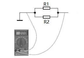
When multiple resistors are linked sequentially in a single pathway, forming a continuous loop, it exemplifies a resistor in a series circuit. This configuration is illustrated in the accompanying diagram featuring two resistors.

Features of the series circuit:
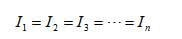
- The current is uniform across every segment of the series circuit, reflecting a singular path for the flow.
- Linking n resistors in series leads to distinct expressions for electrical characteristics.
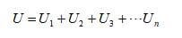
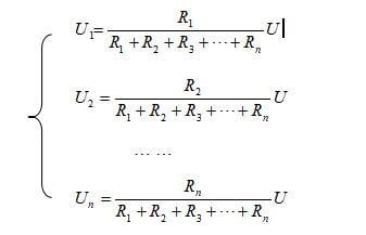
- The aggregate voltage throughout the circuit equals the cumulative sum of the individual voltages across each series resistor.
- Calculating the total resistance entails summing the series resistances, with R being the collective resistance of R1 and R2 in series. Substituting R1 and R2 with R maintains the circuit’s current and voltage distribution intact.
- Refer to Figure 1, where (b) replaces and simplifies (a).
- When n resistors are connected in series, then
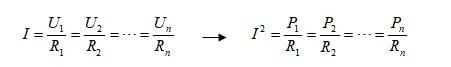
- The voltage and power distribution in series circuits reveals:
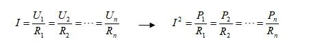
- Voltage across each series-connected resistor mirrors a proportional link to its resistance, similar to the power absorbed by the resistor, illustrated when n resistors form the circuit.
Pro Tip: In real-world scenarios, series resistor arrangements expand a voltmeter’s range, enhancing its usability.
Resistors in Parallel Circuits
Crafted when two or more resistors unite between two points in a circuit, consistently maintaining equal voltage at both endpoints, this setup is known as a resistor in a parallel circuit.

Features of the parallel circuit:
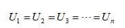
- Each resistor maintains an identical voltage level throughout the circuit.
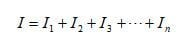
- The circuit's total current is the summation of the currents flowing through individual branches.
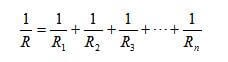
- The inverse of the circuit’s total resistance correlates to the aggregated inverses of the individual resistors.
- Investigating current and power distributions in parallel circuits:
- Within a parallel circuit, each branch's current inversely aligns with its resistance, affecting power consumption alongside.
- For two parallel resistors, branch currents derive from the shunt equation.
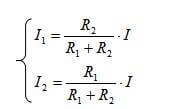
Understanding this formula reveals the tendency for smaller resistances in parallel to channel larger currents, contrasting larger resistances leading to smaller currents.
Observational Insight: Daily applications, such as lighting circuits, favor parallel alignments of electrical devices. This ensures undisturbed operation of other devices when one is unplugged, switched off, or encounters an issue.
Computation of Resistance in Series and Parallel Circuits
Resistors can be arranged both in series and in parallel, alongside several others, creating intricate resistive configurations.
How can one determine the sum of resistance, current, and voltage when diverse resistors are incorporated both parallelly and in series within a circuit?
Circuits comprising both series and parallel resistors are often termed resistor combination or hybrid resistor circuits. The approach to calculate the equivalent resistance mirrors that of individual series or parallel circuits. It becomes evident that series resistors share identical current, while parallel resistors possess the same voltage.
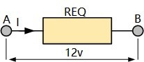
Example Calculation 1
Determine the overall current (IT) sourced from a 12v power supply in the depicted circuit.
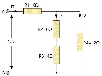
Initially, this task might appear intimidating, but with closer inspection, it reveals that resistors R2 and R3 are in series. Thus, their resistances can be summed:
R2 + R3 = 8Ω + 4Ω = 12Ω
In this manner, R2 and R3 can be substituted with a single 12Ω resistor.
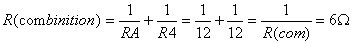
Now, the circuit features resistor RA and resistor R4 parallelly connected. The equivalent resistance value R (combination) for this parallel arrangement is derived using the resistance formula:
The resistive circuit, therefore, morphs to resemble:
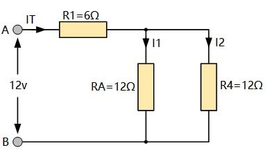
Notably, R1 and R (comb) are in series between points A and B, enabling their addition:
R = R (comb) + R1 = 6Ω + 6Ω = 12Ω
Above all, a 12Ω resistor effectively substitutes the initial four resistors within the original configuration.
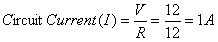
Employing Ohm's law, computing the circuit current value (I) becomes straightforward:
Subsequent to these replacements, a complex resistive circuit of multiple resistors simplifies into one equivalent circuit with a single resistor.
Furthermore, using the Ohm method, two branch currents, I1 and I2, can be obtained:
V(R1) = IR1 = 16 = 6V
V(RA) = V(R4) = (12 - V(R1)) = 6V
Hence:
I1 = 6V ÷ RA = 6 ÷ 12 = 0.5A or 500mA
I2 = 6V ÷ R4 = 6 ÷ 12 = 0.5A or 500mA
Given that both branches feature 12Ω resistances, I1 and I2 each equal 0.5A (or 500mA). As a result, the aggregate supply current IT = 0.5 + 0.5 = 1.0A.
Visual aids, like redrawn circuits integrating complex resistive combinations and networks, often aid conceptual clarity and facilitate calculating an equivalent resistance REQ. Let's tackle a more intricate resistive circuit next.
Example Calculation 2
Calculate the equivalent resistance REQ for the ensuing complex resistive circuit.
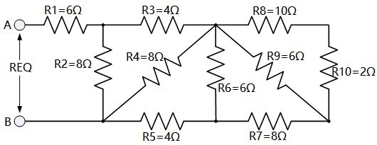
Although this ladder resistor network may initially seem quite daunting, it’s ultimately a series and parallel resistor amalgamation. Starting from the right and simplifying two parallel resistors, derive the collective resistance of R8 and R10, defining it as RA:
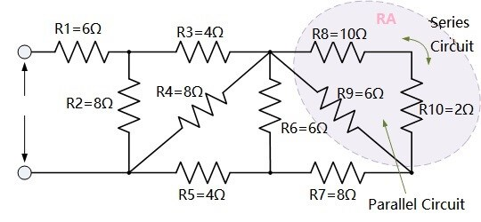
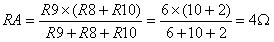
Thus, RA + R7 = 4 + 8 = 12Ω
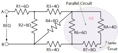
This 12Ω is parallelly positioned with R6, leading to RB's total resistance value:
Subsequently, RB + R5 results in 4 + 4 = 8Ω
Following this, the 8Ω resistance is parallel with R4, refining RC's value:
RC is in series with R3, yielding a summative resistance of RC + R3 = 8Ω, as illustrated.
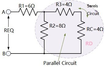
Here, the 8Ω resistance is parallel to R2, enabling RD's computation:
RD links in series with R1, garnering a total resistance of RD + R1 = 4 + 6 = 10Ω shown here.
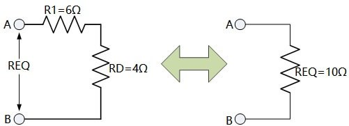
Finally, the initially intricate resistor network, involving ten standalone resistors in series and parallel, is equated to a 10Ω resistance.
When evaluating resistive series and parallel circuits, recognize straightforward series and parallel branches first, then substitute them with single equivalent resistors.
This process diminishes circuit complexity, allowing transformation of compound resistor circuits into a solitary equivalent resistor.
Contrarily, more convoluted configurations like T-pad attenuators and resistance bridges demand Kirchhoff’s laws due to their resistance complexities, defying straightforward series or parallel resolution.
Understanding the Dynamics and Interventions for Resistors in Series and Parallel Circuits
Nuances of Short and Open Circuits in Series Configurations
Intricacies of Short Circuits
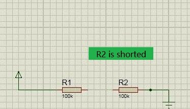
The illustration below depicts a short circuit situation within a series configuration. Initially connected in series, resistors R1 and R2 are impacted as R2 becomes shorted.
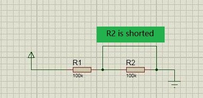
Upon R2 becoming short-circuited, series circuit characteristics change dramatically. Only resistor R1 remains active, causing a shift where total resistance mirrors the resistance of R1 alone.
The unchanged DC voltage +V and the lowered overall resistance usher in heightened current flow through the circuit after R2 gets shorted.
The current increment hinges on R2's attributes; a larger resistance results in a more substantial current surge, potentially triggering overcurrent conditions. This phenomenon risks overwhelming the power source, which could fail due to unsustainable current demands.
Moreover, this burgeoning current affects other resistors like R1, elevating the likelihood of damage due to overcurrent conditions across shared pathways.
Within series circuits, an increased current through an element flags a probable short circuit event. Notably, the amplified current also amplifies voltage drops across unaffected resistors.
Short-circuit scenarios within series circuits represent formidable challenges, threatening collective component integrity due to elevated circuit-wide currents.
Characteristics of Open Circuits
When an open circuit transpires within a series circuit involving a resistor, it halts the current flow entirely, irrespective of the segment rendering it open.
Typically, such faults have minimal repercussions for the series configurations, yet occasional voltage surges in the drive circuit might provoke a failure.
Analyzing Series Resistor Faults
Below, a table summarizes fault assessments for series circuit arrangements involving resistors R1 and R2.
|
Component Name |
Fault Type |
Fault Analysis |
Analyzing Thought |
|
R1 |
Open Circuit |
No
current flows through R1 and R2, and no voltage can be measured across R1 and
R2 |
No
current flows through the resistor, so there is no voltage. |
|
Short Circuit |
The
current flowing through R2 increases, which may burn out R2 |
The
total resistance decreases, which increases the total current. If the current
flowing through R2 is too large, it will burn out R2. |
|
|
Resistance Increased |
The
current flowing through R1 and R2 decreases, the voltage of R1 increases, and
the voltage of R2 decreases. |
After
the resistance of R1 increases, the total resistance increases, the total
current decreases, and the voltage drop of R2 decreases, so the voltage of R1
increases. |
|
|
Resistance Decreased |
The
current flowing through R1 and R2 increases, the voltage of R1 decreases, and
the voltage of R2 increases |
After
the resistance of R1 increases, the total resistance decreases, and the total
current increases, so that the voltage on R1 decreases |
|
|
Poor Contact |
The
circuit will work normally on one occasion, and work abnormally on another. |
The
circuit works normally when contact is normal, the circuit works abnormally
when contact is abnormal |
|
|
R2 |
The Above Five Faults |
Failure
analysis is the same as above (replace R1 with R2) |
The
analytical thinking is the same as above (replace R1 with R2) |
The same faults apply to R2, adopting the aforementioned rationale as R2 replaces R1's position for analysis.
Techniques for Diagnosing Series Resistor Failures
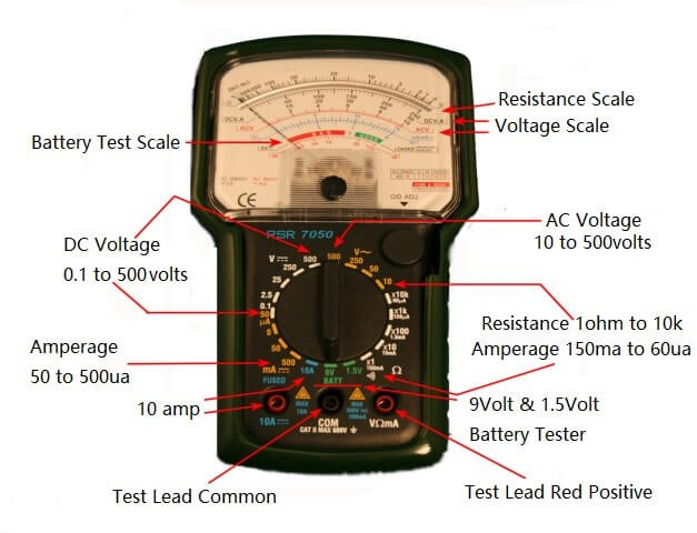
Series circuit failures can be diagnosed through various methodologies. Multimeters, when set to ohm range, enable resistance evaluations across individual resistors. Nonetheless, flexibility in approach optimizes troubleshooting outcomes.
Probing Method for Open Circuit Faults
For DC circuits, utilizing a multimeter's DC voltage setting measures potential across R1 directly, enabling detection of any open circuit disruptions.
AC circuits require the multimeter's AC voltage functionality to gauge the same across R1, pinpointing faults with precision.
Short Circuit Inspection Approach
An analogous method to assess voltage across R1 proves beneficial for short circuit faults in series resistors. Elevated voltages across R1 serve as indicators of circuit anomalies.
However, an inherent challenge resides in discerning irregularities without baseline voltage data, complicating certainty around current fluctuations.
Diagnosing Parallel Resistor Failures
Open Circuit Detection in Parallel Configurations
With the circuit unpowered, employ a multimeter to ascertain total resistance. A typical measurement should reveal values less than R1 and R2 individually.
Surpassing resistance values point to a disconnect within either R1 or R2, warranting further inspection of individual resistance pathways to ascertain clarity.
Addressing Short Circuit Faults
Zero resistance readings hint at a short circuit within parallel arrangements, necessitating granular analysis for precise fault location and causation identification. Conducting thorough assessments frames ensuing troubleshooting strategies.
Understanding Equivalent Series Resistance
Definition and Basic Concept of ESR
Equivalent Series Resistance, abbreviated as ESR, refers to the resistance encountered when resistors are connected in a series configuration. This resistance increases with series connections of resistors and decreases when they are connected in parallel.
Impact of ESR on Capacitor Performance
The introduction of ESR alters the expected behavior of capacitors. In an ideal situation, capacitors do not harbor energy loss. However, due to inherent resistance in the materials and energy loss in the insulation medium, capacitors deviate from perfection. Externally, these losses mimic the presence of a resistor in series, which is encapsulated in the concept of "equivalent series resistance."
Voltage Dynamics in Capacitors
The belief persists that a capacitor's voltage should not instantly change. When a sudden current is applied, the capacitor's voltage naturally ascends from zero as it charges. Nonetheless, with ESR, an immediate voltage drop occurs across the resistor, which triggers an unexpected voltage change in the capacitor, impacting its filtering capability. This degradation prompts the use of low ESR capacitors in superior power supplies.
ESR Influence on Oscillating Circuits
In oscillating circuits, ESR impacts circuit functionality, raising concerns like circuit malfunction or damage.
The Role of ESR in Performance Optimization
Generally, low ESR capacitors outperform their high ESR counterparts, yet situational exceptions exist. Occasionally, ESR contributes beneficially.
ESR and Transient Response in Voltage Stabilization
In voltage stabilization applications, especially under transient load conditions, capacitors with certain ESR levels provoke fluctuations that activate feedback circuits. This rapid response trades off transient performance, particularly when power tube response is sluggish and capacitor size or capacity is limited. This is evident in three-terminal voltage regulators utilizing MOS tubes, where reduced ESR hinders overall performance.
Practical Applications and Solutions
Numerous scenarios demand reduced ESR, making low-ESR capacitors more sought after albeit costlier. Consequently, in various switching power supplies, a parallel setup of aluminum electrolytic capacitors with relatively high ESR is implemented to fabricate a low-ESR capacitor arrangement. This approach balances the increase in PCB space utilization with reduced device expenditure.
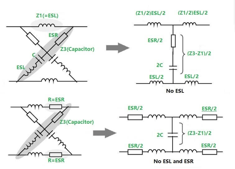
ESL and Its Relation to ESR
ESL, or Equivalent Series Inductance, relates closely to ESR. Historically, dense capacitors bore significant ESL, correlating capacitance with ESL size. Although ESL sometimes merges with ESR, causing circuit complications like series resonance, its capacity-related impact is minimal. Technological advancements have diminished ESL's relevance, with ESR serving as a primary consideration alongside capacitance.
ESL and ESR in Capacitor Optimization
Capacitors also exhibit a quality factor, Q, similar to inductance, inversely related to ESR and frequency-dependent, yet seldom leveraged in practice.
Practical Considerations and Analysis Techniques
ESR-induced circuit issues often evade detection while its impacts can be overlooked during design. A practical approach in simulations involves substituting a minor resistance in series with the capacitor to replicate ESR effects. Typically, Tantalum Capacitors exhibit ESR levels below 100 milliohms, in contrast to higher values found in aluminum electrolytic capacitors. Some capacitors' ESR can even escalate to multiple ohms.
ESR's Relationship with Frequency in Tantalum Capacitors
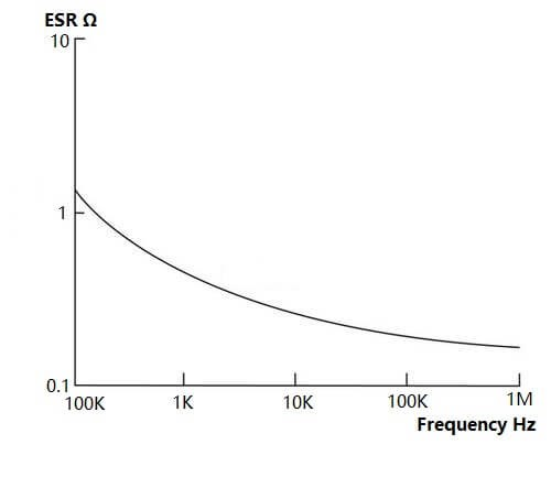
Analyzing the Relationship between ESR and Current
The connection between ESR and ripple voltage is described by:
V = R(ESR) × I
Here, V represents ripple voltage, R is the capacitor's ESR, and I denotes current. It becomes evident that with increasing current, ripple voltage doubles despite a stable ESR.
Frequently Asked Questions [FAQ]
1. How do you find the resistance of a resistor in a series circuit?
When dealing with two resistors or impedances connected in series, and they differ in value, you'll discover that the total resistance, \( R_T \), is simply the sum of the individual resistances. Thus, the equation becomes \( R_T = R_1 + R_2 \).
2. How do you find the current through a resistor in parallel and series?
In a series circuit, the current remains constant throughout each resistor. This current is calculated by dividing the total applied voltage by the equivalent resistance, leading to the formula \( I = \frac{V}{R_S} = \frac{9V}{90Ω} = 0.1A \). Furthermore, the collective voltage drop across each resistor adds up to the battery's overall voltage.
3. How do you find the total resistance in a series parallel circuit?
The sum of currents flowing through each path equals the total current supplied by the source. For a parallel circuit, the total resistance can be determined with this equation: \( \frac{1}{R_t} = \frac{1}{R_1} + \frac{1}{R_2} + \frac{1}{R_3} \ldots \). It's noteworthy that if one pathway in the parallel setup is interrupted, the current persists along other paths.
4. What determines if the resistors are in series or parallel?
Two main factors help in identifying whether resistors are in series or parallel: current and voltage. If resistors exhibit identical voltage across them, they are classified as being in parallel.
5. How do you calculate resistors in series?
To acquire the cumulative resistance of multiple resistors configured in series, simply add their individual resistances. The associated formula is \( R_{total} = R_1 + R_2 + R_3 \) and so on. For instance, consider calculating the total resistance for three resistors arranged in a series.
Related Blog
-
How Many Zeros in a Million, Billion, Trillion?
![How Many Zeros in a Million, Billion, Trillion?]()
July 29th, 2024
Million represents 106, an easily graspable figure when compared to everyday items or annual salaries. Billion, equivalent to 109, starts to stretch t... -
IRLZ44N MOSFET Datasheet, Circuit, Equivalent, Pinout
![IRLZ44N MOSFET Datasheet, Circuit, Equivalent, Pinout]()
August 28th, 2024
The IRLZ44N is a widely-used N-Channel Power MOSFET. Renowned for its excellent switching capabilities, it is highly suited for numerous applications,... -
Battery Temperature Too Low, Charging Stopped. How to Fix It?
![Battery Temperature Too Low, Charging Stopped. How to Fix It?]()
October 6th, 2024
Mobile phone battery charging issues are common but can be effectively managed. Temperature plays a big role in battery efficiency, as smartphone batt... -
BC547 Transistor Comprehensive Guide
![BC547 Transistor Comprehensive Guide]()
July 4th, 2024
The BC547 transistor is commonly used in a variety of electronic applications, ranging from basic signal amplifiers to complex oscillator circuits and... -
Comprehensive Guide to SCR (Silicon Controlled Rectifier)
![Comprehensive Guide to SCR (Silicon Controlled Rectifier)]()
April 22th, 2024
Silicon Controlled Rectifiers (SCR), or thyristors, play a pivotal role in power electronics technology because of their performance and reliability. ... -
LR621, SR621SW, 364, AG1 Battery Equivalents and Replacements
![LR621, SR621SW, 364, AG1 Battery Equivalents and Replacements]()
July 15th, 2024
LR621 and SR621SW button batteries are prevalent in compact electronic devices like watches, small toys, calculators, and remote keys. Multiple manufa... -
Fundamentals of Op-Amp Circuits
![Fundamentals of Op-Amp Circuits]()
December 28th, 2023
In the intricate world of electronics, a journey into its mysteries invariably leads us to a kaleidoscope of circuit components, both exquisite and co... -
Comparing NMOS and PMOS Differences and Applications
![Comparing NMOS and PMOS Differences and Applications]()
November 15th, 2024
Understanding the differences between NMOS and PMOS transistors is important in designing efficient circuits. NMOS (N-type Metal-Oxide-Semiconductor) ... -
A Complete Guide to Multiplexers and Their Role in Digital Systems
![A Complete Guide to Multiplexers and Their Role in Digital Systems]()
September 20th, 2025
Multiplexers are components in digital systems, designed to channel multiple input signals into a single output line using binary logic and control si... -
What Do STD, AGM, and Gel Mean On a Battery Charger
![What Do STD, AGM, and Gel Mean On a Battery Charger]()
July 10th, 2024
Traditional lead-acid battery chargers are known for their simplicity and reliability. They have been serving their purpose effectively for years, lar...


Hot Parts
- 1808GC122KAT1A
- SST39VF020-70-4I-NHE
- GQM1555C2D6R1CB01D
- LM6134BIM/NOPB
- TRS3223CDB
- ISL6235CA
- FAN5091MTC
- AC0805KKX7RYBB103
- C3216X6S0G686M160AC
- MAX388CWG
- 18123D106MAT2A
- MAX3693ECJ+T
- 08052C332KAT2A
- LP3917WL
- ICS9120-08CS08T
- GRM31CR71A226ME15L
- 1812CA182KAT1A
- LD035A430JAB2A
- SI5338C-A-GM
- UPD178076GF-513-3BA
- SN65220DBVT
- ADG439FBRZ
- MC9S12D64VPVE
- M63993FP
- MAX4052EEE
- T495D336K025ATE300
- PF38F1030W0YBQZ
- OARS1R010FLF
- M4-128/64-7YC-10YI
- CGJ3E2C0G1H390J080AA
- VSC8211XVW
- SNC1N21GHK
- KBZ00X001M-A455
- M41T11MH6E
- DG441DY-E3
- PEF55204EV1.2
- SI3015-KS
- 1206AA560KATME
- TAAB226M016G
- VE-234-EV
- BSL205NH6327
- TC200E0601AF-11
- X95820WV
- A6655SJPT
- XC4013XL-PQ208CFN
- LTC1069-6IS8
- PDIUS8D12
- BUK9M24-40E
- ICNTQ28UTGA1
- HI-1565PSI