- English
-
EnglishDeutschItaliaFrançais한국의русскийSvenskaNederlandespañolPortuguêspolski繁体中文SuomiGaeilgeSlovenskáSlovenijaČeštinaMelayuMagyarországHrvatskaDanskromânescIndonesiaΕλλάδαБългарски езикGalegolietuviųMaoriRepublika e ShqipërisëالعربيةአማርኛAzərbaycanEesti VabariikEuskeraБеларусьLëtzebuergeschAyitiAfrikaansBosnaíslenskaCambodiaမြန်မာМонголулсМакедонскиmalaɡasʲພາສາລາວKurdîსაქართველოIsiXhosaفارسیisiZuluPilipinoසිංහලTürk diliTiếng ViệtहिंदीТоҷикӣاردوภาษาไทยO'zbekKongeriketবাংলা ভাষারChicheŵaSamoa日本語SesothoCрпскиKiswahiliУкраїнаनेपालीעִבְרִיתپښتوКыргыз тилиҚазақшаCatalàCorsaLatviešuHausaગુજરાતીಕನ್ನಡkannaḍaमराठी
Exploring the IR2104 Half Bridge MOSFET Driver
The IR2104

IR2104
Infineon Technologies
IC GATE DRVR HALF-BRIDGE 8DIP
In Stock: 19600 pcs
is a compact, high-efficiency gate driver IC built to control both high-side and low-side MOSFETs in half-bridge configurations. It supports 3.3V logic, includes built-in protection features like deadtime and undervoltage lockout, and uses a bootstrap circuit for high-side drive. With its single-PWM input control, robust noise immunity, and RoHS-compliant packaging, the IR2104 is ideal for motor drivers, DC-DC converters, and inverter circuits that demand precise, reliable switching.
Catalog
Overview of the IR2104 Half-Bridge Driver
The IR2104
IR2104
Infineon Technologies
IC GATE DRVR HALF-BRIDGE 8DIP
In Stock: 19600 pcs
IC emerges as a highly efficient half-bridge driver, pivotal for managing the gates of high-power transistors such as MOSFETs. This device adeptly converts low-power inputs into substantial current outputs. It functions as both a level shifter and a power amplifier. It fits smoothly with standard CMOS or LSTTL logic outputs and handles 3.3V logic levels, adding to its adaptability for varied high-and low-side referencing. The IR2104 utilizes cutting-edge technology to address HVC and latch issues, ensuring smooth monolithic integration.
The IR2104 is remarkable in its ability to function with low voltages while delivering strong current outputs. This feature suits high-energy applications well. Its ability to adjust to different circuit needs highlights its flexibility and reliable performance.
In settings, the IR2104 often finds its place in motor control and power conversion systems where precision intertwines with reliability. Its ability to lower power loss is often used in high-efficiency systems. This also helps reduce electromagnetic interference.
Functional Features of the IR2104
The IR2104
IR2104
Infineon Technologies
IC GATE DRVR HALF-BRIDGE 8DIP
In Stock: 19600 pcs
is a practical, high-efficiency MOSFET driver designed for ease of use and dependable operation in switching applications. The internal structure allows steady and quick performance across different electrical conditions, fitting both simple and advanced circuit setups.
Simple and Efficient Control
The driver simplifies control with a single PWM input, enabling straightforward switching without the need for complex signal arrangements. This minimizes external wiring and reduces chances of error in timing control.
For situations, a dedicated shutdown input allows to quickly stop the driver’s activity. When activated, it forces both the high-side and low-side outputs into an off state, ensuring total shutdown and preventing accidental conduction. This feature is ideal for protecting connected devices during fault conditions.
Protection Against Faults and Timing Errors
To avoid damaging overlaps in switching, the IR2104 includes cross-conduction prevention logic. This ensures that both MOSFETs cannot conduct at the same time, a reliable safeguard in power switching systems.
The built-in deadtime circuitry creates a short delay between turning off one transistor and turning on the other. This timing buffer, automatically handled by the driver, avoids brief short circuits across the power supply.
Furthermore, the propagation delay is carefully matched between the high and low channels. This means signals arrive at both outputs nearly simultaneously, reducing timing imbalance and enhancing control precision.
Robust Signal Response and High-Side Drive Support
The high-side output of the driver closely tracks the input PWM signal, resulting in a predictable and clean signal at the gate of the high-side MOSFET. This kind of consistent response is ideal for systems where timing accuracy affects power delivery or waveform integrity.
The IR2104 uses a bootstrap floating channel to support high-side switching. This allows it to drive a high-side MOSFET using just a simple external capacitor, avoiding the need for a dedicated high-voltage gate driver supply. The design handles standard floating node behavior and allows seamless operation in half-bridge configurations.
Stability Under Fast and Harsh Conditions
The driver is built to handle short-duration negative voltage transients without functional disruption, which makes it reliable in electrically noisy environments.
In addition, it exhibits high immunity to fast voltage changes (high dV/dt conditions), maintaining stable operation even when the load or supply fluctuates quickly, a common occurrence in switching power applications.
To protect against supply instability, an undervoltage lockout mechanism is included. If the supply voltage drops below a safe threshold, the driver automatically shuts down the output stages to prevent erratic behavior.
Practical Design for Easy Integration
The hardware is designed with convenience in mind. Screw terminals are provided for output load connections, which makes it easier to attach wires securely in both test and permanent setups.
For control signal access, a pin header connects directly to the logic supply and input lines, enabling fast integration into development boards or control systems.
Lastly, the IR2104 is available in a lead-free, RoHS-compliant version, offering an environmentally responsible choice without compromising electrical performance.
IR2104 Specifications
|
Type |
Parameter |
|
Average load current |
10amps |
|
Peak current |
20amps |
|
VCC voltage range |
12V ~ 36V DC |
|
Logic gate voltage supply |
12-15V DC |
|
Content of compatible input signals |
3.3V-15V |
|
Fully operational |
+600V |
|
Gate drive supply range |
from 10 to 20V |
|
Operating Temperature |
-40°C~150°C TJ |
|
Pinout |
SMD-based design |
|
Package |
8-DIP |
Configuration and Pin Setup

|
Pin No. |
Pin Name |
Description |
|
1 |
VCC |
Logic and internal gate drive supply
voltage |
|
2 |
IN |
Input Pin |
|
3 |
SD |
Shutdown Pin (Active Low) |
|
4 |
COM |
Chip power and signal ground |
|
5 |
LO |
Low side gate driver output |
|
6 |
VS |
High side floating supply return |
|
7 |
HO |
High side gate driver output |
|
8 |
VB |
High side gate driver floating supply |
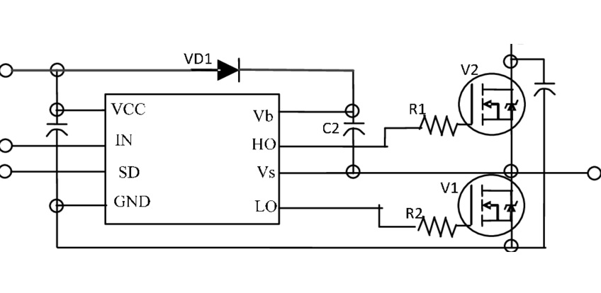
IR2104 Standard Circuit Diagram
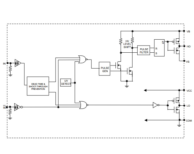
IR2104 Internal Block Diagram
IR2104 Comparable Device
• DGD2104
• IR2103
IR2103
Infineon Technologies
IC GATE DRVR HALF-BRIDGE 8DIP
In Stock: 16580 pcs
• IRS2104

IRS2104
IR
IRS2104 IR
In Stock: 4844 pcs
• IR2153
IR2153
Infineon Technologies
IC GATE DRVR HALF-BRIDGE 8DIP
In Stock: 40407 pcs
• IR2110

IR2110
Infineon Technologies
IC GATE DRVR HALF-BRIDGE 14DIP
In Stock: 3451 pcs
Use Techniques of IR2104
The IR2104
IR2104
Infineon Technologies
IC GATE DRVR HALF-BRIDGE 8DIP
In Stock: 19600 pcs
is designed to control two MOSFETs, one on the high side and one on the low side, using a single PWM signal. This makes it ideal for driving a half-bridge circuit, such as in motor control, DC-DC converters, or inverter applications.
Basic Connections and Power Setup
To begin, connect your PWM signal (often from a microcontroller like the Arduino Uno) to the IN pin of the IR2104. A common configuration uses digital pin D9 on the Arduino. This single input line handles both the high-side and low-side switching operations, simplifying your timing setup.
Power the logic side of the driver by connecting VCC to a 10–20V regulated supply (often 12V), and tie COM directly to the ground of the controller (such as Arduino GND). This establishes a clean reference for signal-level operation.
Enabling and Disabling the Driver
If you want to control whether the gate driver is active or not, use another digital output, for example, Arduino pin D8, and connect it to the SD (Shutdown) pin. Driving this pin low will immediately disable both outputs (HO and LO), shutting down the half-bridge completely. This is a vital safety feature for fault handling or emergency stops.
Bootstrap Setup for High-Side Operation
The IR2104 uses a bootstrap circuit to power the high-side gate driver. To create this, insert a fast-recovery diode between VCC and VB, then place a ceramic capacitor (commonly 0.1µF to 1µF) between VB and VS. This capacitor holds the charge needed to lift the high-side gate above the source voltage, allowing the upper MOSFET to turn on.
It's important that the PWM signal includes short periods when the low-side MOSFET is on. During these intervals, the bootstrap capacitor recharges. If this recharge phase doesn’t occur regularly, the high-side driver will lose power, and switching will fail. A PWM duty cycle below 100% ensures proper bootstrap operation.
Switching Behavior and Signal Timing
Once connected and powered, the IR2104 produces two outputs:
HO (High-Side Output) drives the upper MOSFET.
LO (Low-Side Output) drives the lower MOSFET.
These outputs are timed internally so that both transistors never conduct at the same time. A built-in deadtime is automatically inserted between switching events. This prevents shoot-through conditions, where both MOSFETs could briefly short the supply if turned on simultaneously.
The HO output mirrors the PWM input, but only when the bootstrap circuit is functioning correctly. The LO output activates when the PWM signal goes low, allowing for alternating control of both transistors.
Practical Wiring and Safety Tips
To keep the system stable and noise-free:
• Use short, thick wires for all high-current paths.
• Ensure a solid, low-impedance ground connection from the controller to COM.
• Keep the bootstrap capacitor close to the driver pins to reduce inductive delays.
• Stay within the voltage and current ratings of the IR2104 and connected MOSFETs.
Refer to example circuits in the IR2104 datasheet to see typical bus voltage levels and layout suggestions. These reference designs are built to demonstrate safe operation under real-world electrical conditions.
IR2104 Maximum Ratings
|
Symbol |
Definition |
Min. |
Max. Units |
||
|
VB |
High side floating absolute voltage |
-0.3 |
625 V |
||
|
VS |
High side floating supply offset voltage |
VB - 25 |
VB + 0.3 V |
||
|
VHO |
High side floating output voltage |
VS - 0.3 |
VB + 0.3 V |
||
|
VCC |
Low side and logic fixed supply voltage |
-0.3 |
25 V |
||
|
VLO |
Low side output voltage |
-0.3 |
VCC + 0.3 V |
||
|
VIN |
Logic input voltage (IN & SD) |
-0.3 |
VCC + 0.3 V |
||
|
dVS/dt |
Allowable offset supply voltage transient |
— |
50 V/ns |
||
|
PD |
Package power dissipation @ TA ≤ +25°C |
(8 lead PDIP) |
— |
1.0 W |
|
|
(8 lead SOIC) |
— |
0.625 W |
|||
|
RthJA |
Thermal resistance, junction to ambient |
(8 lead PDIP) |
— |
125 °C/W |
|
|
(8 lead SOIC) |
— |
200 °C/W |
|||
|
TJ |
Junction temperature |
— |
150 °C |
||
|
TS |
Storage temperature |
-55 |
150 °C |
||
|
TL |
Lead temperature (soldering, 10 seconds) |
— |
300 °C |
||
IR2104 Operational Guidelines
|
Parameter |
Condition |
Range |
|
Ambient temperature (TA) |
|
-40 to 125°C |
|
Supply voltage (VS) |
Low side and logic |
10 to 20V |
|
Absolute voltage (VB) |
High side |
VS + 10 to VS + 20 V |
|
Floating output voltage |
High side |
VS to VB |
|
Floating offset voltage |
High side |
Note 1 to 600V |
|
Logic input voltage range |
|
0 to VCC |
|
Output voltage |
Low side |
0 to VCC |
IR2104 Applications and Uses Extended
The IR2104
IR2104
Infineon Technologies
IC GATE DRVR HALF-BRIDGE 8DIP
In Stock: 19600 pcs
integrated circuit finds extensive application across numerous industries, thanks to its ability to operate with high efficiency and adaptability. It demonstrates its versatility prominently in driving DC power supplies, motor controllers, and inverters. It adeptly manages high-power switching devices and supports steady electric power transmission, offering valuable contributions to advanced electronics.
DC Power Supplies
In the field of DC power supplies, the IR2104 enhancing the power conversion systems' efficiency and reliability. It keeps voltage output steady, making it suitable for delicate electronic parts. It also helps reduce energy loss and supports reliable performance across different conditions.
Motor Controllers
Motor controllers benefit immensely from the profound capabilities of the IR2104. Its practical application in precise speed and torque control leads to notable energy savings, especially within industrial contexts. Supporting smooth operations and lowering mechanical wear, it contributes to the sustainability and long-term use of motor-driven systems.
Inverters
Inverters, especially within renewable energy systems, utilize the IR2104 effectively. Its role in facilitating DC to AC power conversion provides pivotal support for devices reliant on such conversions. Exhibiting robust design and reliable performance under variable loads, it strengthens solar power installations and wind turbines, fostering the shift towards eco-friendly energy sources.
The IR2104 extends its applications to novel technologies, suggesting this potential has yet to be fully tapped. As technology continues to advance, the quest for effective power management solutions intensifies, positioning the IR2104 as a strong contender for innovative applications like electric vehicles and smart grids:
Electric Vehicles
In the vibrant electric vehicle market, the IR2104 shines with its proficient handling of high currents and voltages, positioning it as an optimal choice for powertrain systems. It enhances battery management systems, contributing to extended driving ranges and boosted vehicle performance, echoing sustainability ambitions.
Smart Grids
Smart grids, with future prospects heavily reliant on effective power electronics, find the IR2104 instrumental. Its role in introducing renewable energy sources into the grid emphasizes its significant contribution. It aids in peak load management and grid stability, resonating with the increasing demand for more robust and adaptable power distribution networks.
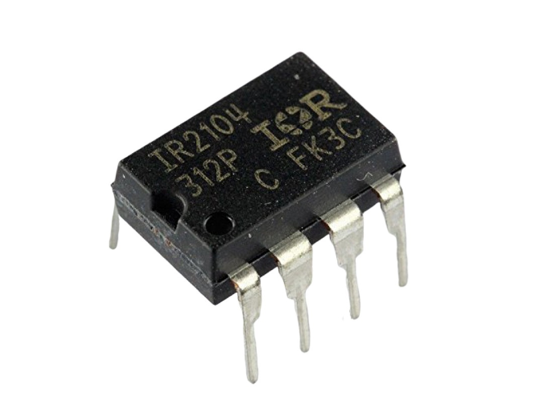
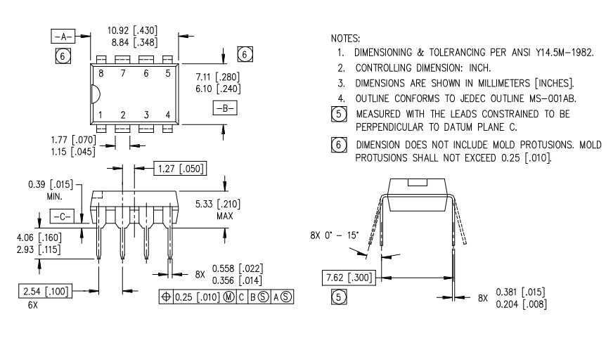
IR2104 Package
The IR2104
IR2104
Infineon Technologies
IC GATE DRVR HALF-BRIDGE 8DIP
In Stock: 19600 pcs
in an 8-pin DIP (Dual Inline Package) with detailed mechanical dimensions. The body width ranges between 8.84 mm and 10.92 mm, while the length measures around 7.11 mm maximum. The standard pin pitch is 2.54 mm, which means it is compatible with common through-hole PCB layouts.
Each of the eight pins has a width between 0.25 mm and 0.36 mm, with spacing carefully defined for stable insertion. The overall pin span across the package is about 7.62 mm, with pins slightly flared outward, allowing for secure soldering. Pin lengths are given as 2.93 mm to 4.06 mm, ensuring enough lead length for through-hole mounting.
It emphasizes tolerances for pin angles (0° to 15°) and coplanarity, ensuring that the part sits flat on a board during assembly. These specifications guarantee reliable electrical connections and mechanical stability when the IR2104 is mounted on standard PCBs.
The Comparison of IR2104 and IR2101
|
Feature |
IR2104
|
IR2101
|
|
High/Low Side Output Control |
Independent outputs (HO, LO) |
Combined or less flexible |
|
Typical Package |
SOIC-8 (Surface Mount) |
DIP-8 (Through-Hole) |
|
Logic Level Compatibility |
CMOS / LSTTL supported |
Not clearly defined |
|
Maximum Bus Voltage |
600 V |
Similar range, less documented |
|
Use Case Fit |
Best for modern, fine-tuned designs |
Suitable for basic switching tasks |
Conclusion
The IR2104
IR2104
Infineon Technologies
IC GATE DRVR HALF-BRIDGE 8DIP
In Stock: 19600 pcs
simplifies complex gate drive tasks in modern power systems by combining flexibility, protection, and ease of integration. Whether you're designing power converters, motor control circuits, or renewable energy systems, this IC offers the performance and durability needed for efficient switching. The IR2104 offers a stable, compact, and reliable solution for half-bridge designs, making it a preferred choice in many applications.
Datasheet PDF
IR2104 Datasheets:
Frequently Asked Questions [FAQ]
1. What does the IR2104 do?
The IR2104 is a gate driver designed to control high-power switching devices like MOSFETs and IGBTs. It can drive both a high-side and a low-side switch in a half-bridge configuration, making it useful for motor control, inverters, and power converters.
2. What is a half-bridge gate driver?
A half-bridge gate driver controls two switches, one on the high side and one on the low side of the circuit. It allows these switches to operate in sequence, safely handling high voltages and fast switching speeds to regulate power flow efficiently.
3. How is IRS2104 different from IR2104?
The IRS2104 is a newer version that switches faster. It has shorter rise and fall times than the IR2104, which helps improve performance in fast-switching circuits.
4. Why isn’t my IR2104 driver working?
Make sure the SD (shutdown) pin is set high, or the chip won’t run. Also, if you’re using a transistor to drive the IN pin, you may need a base resistor. Without it, the input voltage might stay too low to turn the IR2104 on.
5. What’s the difference between half-bridge and full-bridge drivers?
A half-bridge driver controls two switches, one high-side and one low-side. A full-bridge driver controls four switches (two high, two low), allowing current to flow in both directions through the load.
Related Blog
-
How Many Zeros in a Million, Billion, Trillion?
![How Many Zeros in a Million, Billion, Trillion?]()
July 29th, 2024
Million represents 106, an easily graspable figure when compared to everyday items or annual salaries. Billion, equivalent to 109, starts to stretch t... -
IRLZ44N MOSFET Datasheet, Circuit, Equivalent, Pinout
![IRLZ44N MOSFET Datasheet, Circuit, Equivalent, Pinout]()
August 28th, 2024
The IRLZ44N is a widely-used N-Channel Power MOSFET. Renowned for its excellent switching capabilities, it is highly suited for numerous applications,... -
Battery Temperature Too Low, Charging Stopped. How to Fix It?
![Battery Temperature Too Low, Charging Stopped. How to Fix It?]()
October 6th, 2024
Mobile phone battery charging issues are common but can be effectively managed. Temperature plays a big role in battery efficiency, as smartphone batt... -
BC547 Transistor Comprehensive Guide
![BC547 Transistor Comprehensive Guide]()
July 4th, 2024
The BC547 transistor is commonly used in a variety of electronic applications, ranging from basic signal amplifiers to complex oscillator circuits and... -
Comprehensive Guide to SCR (Silicon Controlled Rectifier)
![Comprehensive Guide to SCR (Silicon Controlled Rectifier)]()
April 22th, 2024
Silicon Controlled Rectifiers (SCR), or thyristors, play a pivotal role in power electronics technology because of their performance and reliability. ... -
LR621, SR621SW, 364, AG1 Battery Equivalents and Replacements
![LR621, SR621SW, 364, AG1 Battery Equivalents and Replacements]()
July 15th, 2024
LR621 and SR621SW button batteries are prevalent in compact electronic devices like watches, small toys, calculators, and remote keys. Multiple manufa... -
Fundamentals of Op-Amp Circuits
![Fundamentals of Op-Amp Circuits]()
December 28th, 2023
In the intricate world of electronics, a journey into its mysteries invariably leads us to a kaleidoscope of circuit components, both exquisite and co... -
Comparing NMOS and PMOS Differences and Applications
![Comparing NMOS and PMOS Differences and Applications]()
November 15th, 2024
Understanding the differences between NMOS and PMOS transistors is important in designing efficient circuits. NMOS (N-type Metal-Oxide-Semiconductor) ... -
A Complete Guide to Multiplexers and Their Role in Digital Systems
![A Complete Guide to Multiplexers and Their Role in Digital Systems]()
September 20th, 2025
Multiplexers are components in digital systems, designed to channel multiple input signals into a single output line using binary logic and control si... -
What Do STD, AGM, and Gel Mean On a Battery Charger
![What Do STD, AGM, and Gel Mean On a Battery Charger]()
July 10th, 2024
Traditional lead-acid battery chargers are known for their simplicity and reliability. They have been serving their purpose effectively for years, lar...


Hot Parts
- CRCW0805130KFKEA
- T491B156K016ZT7280
- GRM0336S1E3R5CD01D
- TLC5733AIPM
- CD74HCT157M96
- GJM0335C1E2R0BB01D
- TPSD107M010Y0100
- MIC3975-5.0BMM
- TAP335M035BRS
- GRM1555C1H7R9BZ01D
- XRT86VL34IB-F
- AT42QT1010-TSHR
- CC1812JKX7R9BB184
- ADA4932-2YCPZ-R2
- ISO7760DBQ
- RT0805BRD07187RL
- CYUSB3324-88LTXC
- DS10CP152QMAX/NOPB
- B5P-VH-FB-B
- ADR421AR
- TM4C1233H6PZIR
- UPD78F0500MC-5A4-A
- GRM0335C1H9R9BD01D
- ICL3232CB
- X9259UV24-2.7
- UPA2352BT1G-E4
- IDTQS32X861Q1
- HUF76105DK8T136
- K4D263238E-VC33
- SK6211BBPC-A
- PS2801C-1
- UPD703031BGF-A03-3BA-A
- LTC3708EUH#PBF
- M30622MA-A26FP
- W9812G2GH-75
- 29LV160TE-90PFTN
- M82720G-14
- LTC1729CMS8-8.2
- TLE6210G-C1
- ICS84330BY
- K9WAG08U1B-PCBO
- CMZ5360B
- LPC1833FET256
- NL5512DS-166
- P89LPC938FA68
- TFDS4500
- AM486DX4-133V16BHC
- R5S726A0P216FP
- X8821T-PSN-L
- EEUFR1C102L