- English
-
EnglishDeutschItaliaFrançais한국의русскийSvenskaNederlandespañolPortuguêspolski繁体中文SuomiGaeilgeSlovenskáSlovenijaČeštinaMelayuMagyarországHrvatskaDanskromânescIndonesiaΕλλάδαБългарски езикGalegolietuviųMaoriRepublika e ShqipërisëالعربيةአማርኛAzərbaycanEesti VabariikEuskeraБеларусьLëtzebuergeschAyitiAfrikaansBosnaíslenskaCambodiaမြန်မာМонголулсМакедонскиmalaɡasʲພາສາລາວKurdîსაქართველოIsiXhosaفارسیisiZuluPilipinoසිංහලTürk diliTiếng ViệtहिंदीТоҷикӣاردوภาษาไทยO'zbekKongeriketবাংলা ভাষারChicheŵaSamoa日本語SesothoCрпскиKiswahiliУкраїнаनेपालीעִבְרִיתپښتوКыргыз тилиҚазақшаCatalàCorsaLatviešuHausaગુજરાતીಕನ್ನಡkannaḍaमराठी
A Complete Guide to the IR2110 Gate Driver: Features, Architecture, and Applications
Catalog
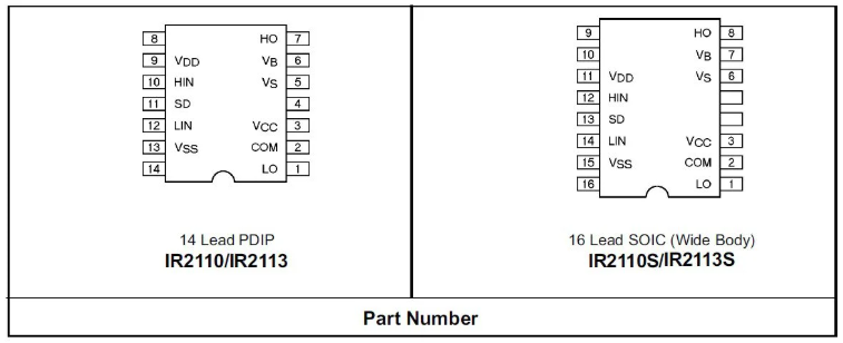
The IR2110 Pinout
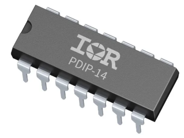
Manufactured by Infineon Technologies, the IR2110 is available in two primary IC package types: the plastic dual in-line package (PDIP) and the small outline integrated circuit (SOIC) package. The consistent pin configurations across these packages invite straightforward integration into various systems, requiring minimal adjustments. Compatibility also extends to the IR2113, designed with faster switching and higher voltage capabilities, providing engineers with options that suit their specific application approaches.
|
IR2110 PINOUT SPECIFICATIONS |
||
|
Label |
Pin No. PDIP|SOIC |
Description |
|
LO |
1|1 |
Low side gate drive output |
|
COM |
2|2 |
Low side return |
|
VCC |
3|3 |
Low side supply |
|
VS |
5|6 |
High side floating supply return |
|
VB |
6|7 |
High side floating supply |
|
HO |
7|8 |
High side gate drive output |
|
VDD |
9|11 |
Logic supply |
|
HIN |
10|12 |
Logic input for high side gate
driver output (HO), in phase |
|
SD |
11|13 |
Logic input for shutdown |
|
LIN |
12|14 |
Logic input for low side gate
driver output (LO), in phase |
|
VSS |
13|15 |
Logic ground |
Architecture and Characteristics of the IR2110
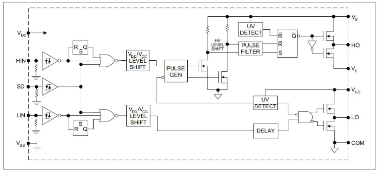
The IR2110 contains a meticulously engineered internal layout, optimizing the operation of both high and low sides. This design enhances efficiency and minimizes risks tied to cross conduction via its powerful high-current buffer. The architecture exemplifies the IR2110's skill in managing distinct drive requirements for the high and low sides, a feature consistently evaluated in practical applications where performance stability is essential under varying conditions.
Additionally, adaptive circuit features provide resilience to variations in load demands, contributing to reliability in power electronics. These designs embody practical insights gathered from comprehensive testing and iterative design processes, aiming to refine power management strategies.
Distinctive Attributes and Applications of the IR2110
The IR2110 boasts an array of distinctive characteristics that enable its wide-ranging use:
- Crafted for bootstrap operation reaching up to +500 V, ensuring operational integrity in environments of elevated voltage.
- Compatible with 3.3 V logic levels, which simplifies its integration with contemporary systems.
- Offers a gate drive supply that spans from 10 to 20 V, facilitating varied power management scenarios.
- Features undervoltage lockout on both channels, significantly boosting reliability by averting malfunction under low voltage situations.
- Contains CMOS Schmitt-triggered inputs and cycle-by-cycle edge-triggered shutdown logic, providing superior control and precision.
These features make the IR2110 exceptionally fitting for a broad spectrum of applications. In automotive power systems, it fulfills demands for efficiency and reliability; in industrial drives, it supports durable and precise motor control. Furthermore, its usage is extended to robotics and satellite communications, both of which necessitate high flexibility and adherence to demanding performance criteria. In mobile security systems and motor drives, the IR2110's design accommodates rapid response and robust functionality. It further demonstrates its versatility in power tools and battery management systems by maintaining consistent performance and prolonging component life. This adaptive versatility permits the IR2110 to excel across multiple technological domains, underscoring its significance in innovative applications.
Technical Specifications
When utilizing the IR2110 (and IR2113), the following restrictions apply.
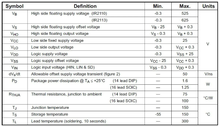
Absolute Maximum Ratings
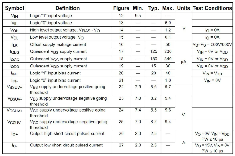
Static electrical characteristics of the IR2110
Other important characteristics to ensure accurate timing and synchronization are:
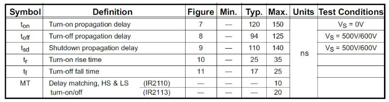
Dynamic electrical characteristics of the IR2110
Crafting PCBA with the IR2110 Gate Driver
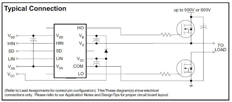
Grasping Circuit Configuration and Application Scenarios
When utilizing the IR2110 for designing printed circuit board assemblies (PCBA), understanding the foundational circuit setup can be quite beneficial. This driver, characterized by its adaptable pin architecture and intricate functional specifications, plays vital roles in MOSFET and IGBT usages across varied sectors including automotive and renewable energy. It's valuable to delve into not just the basic technical components but also the expansive usability in numerous scenarios that utilize its reliability and robustness.
Precision in CAD Models and Manufacturing Process Data
For an efficient creation process and dependable production of PCBAs, employing precise, manufacturer-endorsed CAD models along with detailed manufacturing information can be advantageous. Such resources help execute designs that boost component reliability and enhance project success. For example, strict adherence to CAD design principles accelerates troubleshooting while fostering innovation, enabling smooth integration with diverse systems.
Improving Implementation through Proven Strategies
In the real-world setting of PCBA development using the IR2110 driver, insights gained from applied experience can be quite useful. A practical approach involves optimizing the arrangement of components to reduce electromagnetic interference and enhance thermal management, directly uplifting the PCB’s overall efficacy. Furthermore, comprehensive testing procedures, in line with industry standards, ensure that the designs fulfill functional requirements before proceeding to mass production.
Diverse Insights on Component Reliability and Design Results
Given the interactions between design elements, exploring the fusion of tried practices with novel methods can lead to superior component reliability and improved design results. For instance, incorporating feedback from multiple teams can offer multifaceted perspectives that traditional, single-focus design strategies might overlook. This interdepartmental cooperation often plays a significant role in refining design parameters and successfully implementing robust PCBA solutions.
Related Blog
-
How Many Zeros in a Million, Billion, Trillion?
![How Many Zeros in a Million, Billion, Trillion?]()
July 29th, 2024
Million represents 106, an easily graspable figure when compared to everyday items or annual salaries. Billion, equivalent to 109, starts to stretch t... -
IRLZ44N MOSFET Datasheet, Circuit, Equivalent, Pinout
![IRLZ44N MOSFET Datasheet, Circuit, Equivalent, Pinout]()
August 28th, 2024
The IRLZ44N is a widely-used N-Channel Power MOSFET. Renowned for its excellent switching capabilities, it is highly suited for numerous applications,... -
Battery Temperature Too Low, Charging Stopped. How to Fix It?
![Battery Temperature Too Low, Charging Stopped. How to Fix It?]()
October 6th, 2024
Mobile phone battery charging issues are common but can be effectively managed. Temperature plays a big role in battery efficiency, as smartphone batt... -
BC547 Transistor Comprehensive Guide
![BC547 Transistor Comprehensive Guide]()
July 4th, 2024
The BC547 transistor is commonly used in a variety of electronic applications, ranging from basic signal amplifiers to complex oscillator circuits and... -
Comprehensive Guide to SCR (Silicon Controlled Rectifier)
![Comprehensive Guide to SCR (Silicon Controlled Rectifier)]()
April 22th, 2024
Silicon Controlled Rectifiers (SCR), or thyristors, play a pivotal role in power electronics technology because of their performance and reliability. ... -
LR621, SR621SW, 364, AG1 Battery Equivalents and Replacements
![LR621, SR621SW, 364, AG1 Battery Equivalents and Replacements]()
July 15th, 2024
LR621 and SR621SW button batteries are prevalent in compact electronic devices like watches, small toys, calculators, and remote keys. Multiple manufa... -
Fundamentals of Op-Amp Circuits
![Fundamentals of Op-Amp Circuits]()
December 28th, 2023
In the intricate world of electronics, a journey into its mysteries invariably leads us to a kaleidoscope of circuit components, both exquisite and co... -
Comparing NMOS and PMOS Differences and Applications
![Comparing NMOS and PMOS Differences and Applications]()
November 15th, 2024
Understanding the differences between NMOS and PMOS transistors is important in designing efficient circuits. NMOS (N-type Metal-Oxide-Semiconductor) ... -
A Complete Guide to Multiplexers and Their Role in Digital Systems
![A Complete Guide to Multiplexers and Their Role in Digital Systems]()
September 20th, 2025
Multiplexers are components in digital systems, designed to channel multiple input signals into a single output line using binary logic and control si... -
What Do STD, AGM, and Gel Mean On a Battery Charger
![What Do STD, AGM, and Gel Mean On a Battery Charger]()
July 10th, 2024
Traditional lead-acid battery chargers are known for their simplicity and reliability. They have been serving their purpose effectively for years, lar...


Hot Parts
- 82P2284BBG
- HD64F7046FW50V
- LULXT9785MBC.DO
- CY2148-45DMB
- SSTV16857DGG
- SAB80C517A-N18-T3
- TB6568KQ
- G3203B51U
- MB15F02L
- TEA1506T
- AD8643ARZ
- XRD9827ACU-F
- IDTQS3245QG8
- RT9080-33GQZ
- SST26VF032B-104I/TD
- LT3476EUHF#TRPBF
- NPIC6C595D
- 06035A100FA16A
- T495X336K025ZTE200
- MC34PF3001A3EP
- PN5120A0HN1/C2
- R8A02030A91FP
- C1608X5R2A332M080AA
- SAA7173HL/203
- FMMT718TA
- LTC3851AIMSE-1#TRPBF
- LC87F5WC8AVU-QIP-H
- 1SMA5930BT3G
- PTWL3016B2GQWR
- NCV1413DR2G
- T491V106M035ATAUTO7280
- T491B106K016AT4280
- TUSB212RWBT
- DKA30B-15
- AT32UC3A1256-U
- EPC4QC100T
- HM2110ZNLT
- ISPLSI2032-110LJ
- K9F5608U0D-JIBO
- PPC405GP-3BE266CZ
- STC15W408AS-35I-TSSOP20
- BGA725L6
- R2J12204M4-A05FP
- MD180525
- S19203CBI20
- SFH303FA-3/4
- KDE2405PFB1-8
- LTC4364IDE-2
- MGDS-10-J-C
- PMC8818T