- English
-
EnglishDeutschItaliaFrançais한국의русскийSvenskaNederlandespañolPortuguêspolski繁体中文SuomiGaeilgeSlovenskáSlovenijaČeštinaMelayuMagyarországHrvatskaDanskromânescIndonesiaΕλλάδαБългарски езикGalegolietuviųMaoriRepublika e ShqipërisëالعربيةአማርኛAzərbaycanEesti VabariikEuskeraБеларусьLëtzebuergeschAyitiAfrikaansBosnaíslenskaCambodiaမြန်မာМонголулсМакедонскиmalaɡasʲພາສາລາວKurdîსაქართველოIsiXhosaفارسیisiZuluPilipinoසිංහලTürk diliTiếng ViệtहिंदीТоҷикӣاردوภาษาไทยO'zbekKongeriketবাংলা ভাষারChicheŵaSamoa日本語SesothoCрпскиKiswahiliУкраїнаनेपालीעִבְרִיתپښتوКыргыз тилиҚазақшаCatalàCorsaLatviešuHausaગુજરાતીಕನ್ನಡkannaḍaमराठी
A Complete Guide to Square Wave Generators Using the 555 Timer
Catalog
Overview of Square Wave Generators
Square wave generators are used in electronic circuits, efficiently creating waveforms characterized by swift transitions between high and low voltage levels. These waveforms serve digital electronics by embodying binary states, 1s and 0s, supporting myriad digital and timing functions that are fundamental to contemporary tech ecosystems.
In digital systems, square wave generators are ideal for marking transitions that define binary states, enabling synchronization in communication systems, and providing required timing signals. In microprocessors, they regulate clock speed, which influences computational performance.
Generators create pulse-width modulation (PWM) signals that manage the operation of motors, LEDs, and similar devices. This flexibility fits everything from basic projects to advanced aerospace systems. In many fields, the role of generators is recognized as essential for achieving smooth control and steady performance.
An examination of the mathematics reveals the roles of frequency and duty cycle in the generator's operation. Frequency determines oscillation rates, while the duty cycle, indicating the portion of time the signal stays high in a cycle, affects its functionality, from high-frequency communication to manipulating low-frequency controls.
With attention to detail, experts fine-tune these parameters to meet desired output configurations, showing not only the generator's adaptability but also its compatibility with other systems, where precise timing is essential for optimal operation.
Despite their usefulness, square wave generators encounter obstacles such as signal distortion and electromagnetic interference (EMI). Techniques such as shielding and filtering are often used to reduce noise and improve signal quality. These methods come from practical experience gained through practical work.
The focus in this discipline is on boosting the stability and precision of square wave signals. Cutting-edge technologies address historical constraints, enhancing these generators' reliability and flexibility in more intricate environments, reflecting a path driven by both technical advances and practical necessity.
The Multifaceted Nature of the 555 Timer
The 555 timer IC stands out due to its adaptability and reliability, ideal in a wide array of electronic applications. It transitions seamlessly from basic timer circuits to complex waveform generators, showcasing its varied utility in electronics. Functioning in three unique modes, astable, monostable, and bistable, the 555 timer offers diverse functionalities that shows its flexibility.
Astable Mode
In astable mode, the 555 timer continuously switches between high and low states, effectively producing square waves. These waves find considerable use in clocks and pulse-width modulation applications. Resistors and capacitors in the circuit are often adjusted to set the frequency and duty cycle of the output waveform. This process shows careful tuning to meet the needs of each specific application.
Monostable Mode
Differing from astable mode's perpetual oscillation, monostable mode delivers a solitary output pulse for a set duration when triggered externally. This feature proves beneficial in scenarios demanding precise timing events, such as delay circuits or switch debouncing. The deliberate crafting of a circuit in monostable mode ensures consistent and accurate pulse duration, a factor often appreciated in practical timing applications.
Bistable Mode
The bistable mode provides the 555 timer with the capability to hold a high or low state indefinitely until an external trigger prompts a change. This characteristic is advantageous in scenarios that require a straightforward memory function, akin to a basic flip-flop. This mode is used to create efficient toggle switches in digital logic circuits, and its ability to keep outputs steady is highly valued.
By probing into these modes, one gains insight into the 555 timer's dedication to meeting varying electronic demands. Its three operational modes offer a depth of understanding into its significant applicability, reinforcing its role in both simple and intricate electronic designs. For those seeking more detailed knowledge, exploring a comprehensive 555 Timer guide is recommended.
Designing a Square Wave Circuit Using the 555 Timer
The 555 timer IC stands as a highly adaptable component in electronics, utilized extensively for producing precision timing and generating waveforms. In its astable mode, the IC transitions seamlessly between high and low states, creating a continuous square wave signal. Its straightforward design and functionality have solidified its place in educational and exploratory electronic setups.
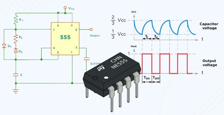
To construct an astable multivibrator using a 555 timer, start by linking pin 8 and pin 4 to the positive voltage source, ensuring the IC is empowered to operate efficiently. Pin 1 should be attached to the ground to finalize the power connection.
A stable operation requires that pin 5 be connected to ground with a small capacitor, which helps nullify potential disturbances from the control voltage and ensures consistent output. By bridging pins 2 and 6 directly, the circuit is set to self-trigger, allowing it to continuously generate a square wave independently.
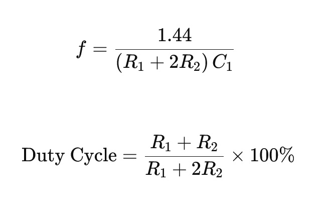
In practice, adjusting the values of two resistors (R1 and R2) alongside a capacitor (C1) connected to pins 7 and 6/2 will determine the output waveform's frequency and duty cycle. The task of selecting suitable resistor and capacitor values revolves around computations based on these formulas:
This selection often involves a hands-on approach, experimenting with various component values to align with circuit specifications.
The square wave resulting from pin 3 serves diverse applications like LED flashers, tone generators, or clock signals in microcontrollers. During the design phase, it might be captivating to weigh the impact of the driven load on output quality, as a heavy load could distort the waveform and reduce the circuit's performance.
The inherent adaptability of the 555 timer offers advantages during prototyping, as altering component values provides the liberty for swift modifications. For complex circuit requirements, integrating additional components to filter or reshape the output signal can elevate performance in applications demanding high precision. Practical experience suggests that placing decoupling capacitors near the IC can effectively minimize noise, ensuring stable frequency output.
Functioning of the 555 Square Wave Generator
Power-Up Sequence and Flip-Flop Reset Dynamics
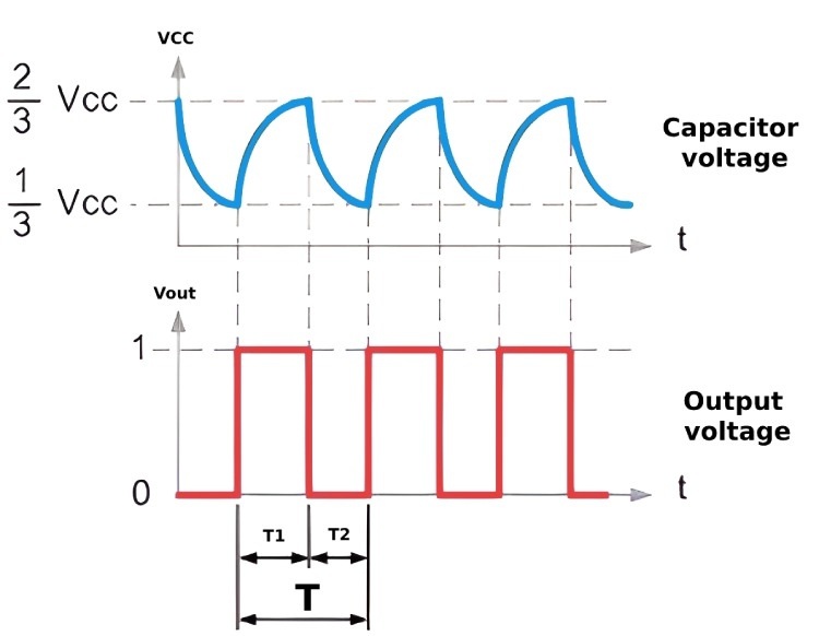
Upon the initial activation of the 555 timer circuit, a foundational setup takes shape when the flip-flop resets. This transition inherently drives the output into a low state and energizes the discharge transistor. At this juncture, the capacitor embarks on a journey of discharging through the transistor, laying the groundwork for the cyclical creation of square waves. In practical applications, maintaining consistent power can avert unpredictable responses during this phase, influencing the circuit's performance in a meaningful way.
Dynamics of Capacitor Charging and Discharging
As the capacitor's voltage diminishes to a point below a third of the supply voltage, an intriguing shift unfolds. The timer's output elevates to a high state, leading to the discharge transistor becoming inactive. This adjustment permits the reinvigoration of the capacitor via a pair of resistors. This step regulates the oscillation frequency, and choosing the right resistor values fine-tunes the frequency's stability and accuracy, adjustments that are often reflective of the circuit’s specialized uses.
Voltage Levels and Flip-Flop State Transition Mechanism
Once the voltage across the capacitor surpasses the two-thirds supply voltage mark, a recalibration occurs as the flip-flop resets, reverting the output to a low state. This cycle reinitiates the activity of the discharge transistor, allowing for continual cycling. This intrinsic toggling shows how steadfast threshold levels ensure the dependable function of 555 timers. In applications, grasping these thresholds can provide valuable insights, especially in scenarios demanding precise pulse timing control, such as PWM signal generation or frequency modulation systems.
Creation of Rectangular Pulses
The persistent charging and discharging pattern of the capacitor, governed by external resistor-defined timing intervals and the 555 timer’s inherent properties, culminates in generating rectangular output pulses. These pulses serve as clock signals or triggers across diverse electronic contexts. Knowledge gleaned from practical settings shows that tweaking timing components allows for customization of pulse width and frequency, enhancing the adaptability of the 555 timer across a multitude of circuit applications.
Calculating Frequency for the 555 Timer
Determining the output frequency of a 555 timer involves an exploration of the components that define its operation, shaping the oscillators and timers in diverse electronics projects. The formula:
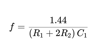
lays bare the intricate dance between resistors (R1), (R2), and capacitor (C1). While online tools like our 555 Timer Astable Circuit Calculator provide quick solutions, delving into the components of this formula can deepen one's understanding of practical circuit design.
The interplay of (R1), (R2), and (C1) forms the backbone of frequency optimization. (R1) acts as the initial charge provider, with (R2) introducing variability that affects the duty cycle. In contrast, (C1) directs the charge time. As circuit designs are improved through repeated testing and careful adjustments, the process becomes a hands-on path that blends practical work with theoretical ideas. With experience gained from long practice in electronics, reaching the desired performance turns into a detailed and thoughtful task.
Applying the frequency formula involves traversing the landscape of environmental influences, such as temperature and voltage fluctuations, which may impact component behavior. Safety margins are commonly added to handle these influences and maintain dependable operation in different applications. Studying how these factors interact can reveal ways to improve circuit strength and performance under a wide range of conditions.
The versatility of the 555 timer transcends mere frequency generation, extending to areas like pulse-width modulation and tone generation. Testing these configurations invites a foray into novel solutions for intricate design challenges. Innovative adaptation can allow established methodologies to evolve, mirroring a perpetual dialogue between tradition and innovation within the field. Such advances show the ever-present need for continuous learning and adaptation in electronics. Examining these dimensions can spark creativity, leading to the genesis of innovative solutions and reflecting the ceaseless evolution of technological exploration.
Achieving the Perfect Square Wave
Configuring a 555 timer to produce a square wave with a 50% duty cycle requires thoughtful adjustments. The standard arrangement typically creates a duty cycle exceeding 50%, which can complicate projects that require exact timing. This necessitates a deep understanding of the circuit's behavior and thoughtful intervention.
Integrating two diodes into the circuit effectively mitigates these disparities. These diodes ensure the capacitor charges and discharges symmetrically, a detailed element that fosters a consistent duty cycle. This process is reminiscent of real-life enhancements in electronic design, aiming to perfectionate component performance.
Adjusting resistor values is a technique for refining the frequency and duty cycle of the output wave. This process is similar to customizing components in electronic design to satisfy particular performance needs. Successfully navigating these parameters combines theoretical knowledge with hands-on experimentation, akin to the creation of a masterful mechanical piece.
In this setup, the pathways charted by the resistors and diodes dictate the capacitor's charge-discharge cycle, mirroring challenges where precision is important in circuit design. This method exemplifies a reliable strategy to achieve precise duty control, echoing the exactness necessary in crafting intricate machinery.
Benefits of the 555 Square Wave Generator
Using a 555 timer to create square waves provides many useful advantages, making it a widely favored choice in various electronics projects, from beginner-level builds to advanced designs.
Simplicity and Approachability
A major benefit is the ease and straightforwardness of its implementation. The 555 timer circuit's simple design means it can be put together with minimal hassle, even for newcomers to the world of electronics. Quickly grasping its operation sidesteps the steep learning curve that comes with more intricate systems. This simplicity creates an encouraging learning atmosphere, allowing individuals to develop self-assurance as they dive deeper into electronic experimentation and innovation. The needed parts, including the 555 timer IC, are inexpensive and easy to find in most electronics stores. This keeps experimentation and project development accessible, even when working with limited funds.
Flexible Adaptability
The square wave generator's flexibility shines through in its adaptability. Users can easily adjust the output waveform's frequency and duty cycle to satisfy specific needs. This flexibility is extremely useful across a wide range of applications, from basic LED blinking circuits to intricate pulse width modulation (PWM) tasks. The ease with which users can modify essential parameters without extensive changes to the circuit design offers a powerful tool for prototyping and refining their projects.
Dependability and Consistency
The dependable and stable nature of the 555 timer ensures reliable performance in various applications. Its proven track record in both educational and practical settings shows its ability to consistently deliver required outcomes. The timer’s resilience across different operating conditions makes it a reliable choice for projects demanding consistent precision. Such endeavors greatly benefit from a component capable of sustaining stable output without the need for frequent recalibration.
Applications of Square Wave Generators
Square wave generators are highly adaptable tools serving a multitude of purposes across various technological arenas. Here are some fascinating applications:
Digital Circuit Clock Signals
In the orchestration of digital circuits, square wave generators create the rhythmic clock signals that harmonize microprocessor operations, facilitating the execution of complex instructions. The reliability of these signals profoundly influences computing efficacy, crafting circuits that thrive under a steadfast clock signal, thereby minimizing errors and boosting system reliability. Attentive to external influences like temperature fluctuations and electromagnetic interference, it can enhance generator performance for uniformity.
Pulse Width Modulation (PWM) Signals
Square wave generators are instrumental in producing PWM signals pivotal for the detailed control of devices like motors and LEDs. By deftly modulating voltage and current, these signals enable fine-tuning of light brightness or motor speed. This method works well in situations where energy must be conserved. Careful adjustment of PWM duty cycles helps reach the needed performance while reducing power consumption. This balance is especially valuable in battery-powered devices.
Audio Signals
In audio signal creation, particularly within sound synthesis and electronic music, square waves are indispensable. Their profound harmonic richness makes them a preferred choice for crafting diverse timbres in synthesizers. Square-wave signals are used to shape new sounds, with layers often combined through filtering techniques to form the desired harmonic character. These methods help create unique audio effects that match specific artistic goals.
Frequency Modulation in Communications
Square wave generators are used in frequency modulation within communication systems, an intricate process essential for transmitting data over various expanses. The simplicity of forming square waves makes them a favored choice for modulating carrier signals in digital communications, where data integrity and transmission speed are required.
Tone Generation in Audio Devices
From alert signals in electronic systems to the whimsical sound effects in toys and gadgets, square wave generators bring forth diverse tones within audio devices. Their ability to produce uniform and precise tones is invaluable for crafting specific auditory cues, enabling distinctions between alert intensities or producing distinctive sound patterns.
Signal Testing in Laboratories
In the field of laboratories, square wave generators become quintessential in testing and calibrating equipment. By offering a steady signal source, it can scrutinize instrument performance and precision across varied conditions, demanding an intricate grasp of equipment specifications and environmental factors that might sway signal conduct, fostering more exact and trustworthy measurements.
LED and Motor Driver Circuits
In LED and motor driver circuits, square waves govern brightness and speed. These signals provide simple yet effective control pathways ideal for applications needing flexible adjustments. Insights gathered from operational feedback are used to improve system adaptability and responsiveness. These improvements help the system maintain strong performance even as operating conditions change.
Conclusion
From powering clock signals in microcontrollers to enabling PWM for motors and LEDs, square wave generators, especially those built with the 555 timer, offer a dependable solution for countless electronic functions. Their ease of design, adjustable output, and consistent performance make them ideal for both learning and professional use. As circuit needs evolve, the adaptability of the 555 timer continues to support innovation in signal generation across digital, audio, and control applications.
Related Blog
-
How Many Zeros in a Million, Billion, Trillion?
![How Many Zeros in a Million, Billion, Trillion?]()
July 29th, 2024
Million represents 106, an easily graspable figure when compared to everyday items or annual salaries. Billion, equivalent to 109, starts to stretch t... -
IRLZ44N MOSFET Datasheet, Circuit, Equivalent, Pinout
![IRLZ44N MOSFET Datasheet, Circuit, Equivalent, Pinout]()
August 28th, 2024
The IRLZ44N is a widely-used N-Channel Power MOSFET. Renowned for its excellent switching capabilities, it is highly suited for numerous applications,... -
Battery Temperature Too Low, Charging Stopped. How to Fix It?
![Battery Temperature Too Low, Charging Stopped. How to Fix It?]()
October 6th, 2024
Mobile phone battery charging issues are common but can be effectively managed. Temperature plays a big role in battery efficiency, as smartphone batt... -
BC547 Transistor Comprehensive Guide
![BC547 Transistor Comprehensive Guide]()
July 4th, 2024
The BC547 transistor is commonly used in a variety of electronic applications, ranging from basic signal amplifiers to complex oscillator circuits and... -
Comprehensive Guide to SCR (Silicon Controlled Rectifier)
![Comprehensive Guide to SCR (Silicon Controlled Rectifier)]()
April 22th, 2024
Silicon Controlled Rectifiers (SCR), or thyristors, play a pivotal role in power electronics technology because of their performance and reliability. ... -
LR621, SR621SW, 364, AG1 Battery Equivalents and Replacements
![LR621, SR621SW, 364, AG1 Battery Equivalents and Replacements]()
July 15th, 2024
LR621 and SR621SW button batteries are prevalent in compact electronic devices like watches, small toys, calculators, and remote keys. Multiple manufa... -
A Complete Guide to Multiplexers and Their Role in Digital Systems
![A Complete Guide to Multiplexers and Their Role in Digital Systems]()
September 20th, 2025
Multiplexers are components in digital systems, designed to channel multiple input signals into a single output line using binary logic and control si... -
Fundamentals of Op-Amp Circuits
![Fundamentals of Op-Amp Circuits]()
December 28th, 2023
In the intricate world of electronics, a journey into its mysteries invariably leads us to a kaleidoscope of circuit components, both exquisite and co... -
Comparing NMOS and PMOS Differences and Applications
![Comparing NMOS and PMOS Differences and Applications]()
November 15th, 2024
Understanding the differences between NMOS and PMOS transistors is important in designing efficient circuits. NMOS (N-type Metal-Oxide-Semiconductor) ... -
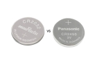
CR2450 vs CR2032 Comparison: All You Need to Know
![CR2450 vs CR2032 Comparison: All You Need to Know]()
September 15th, 2025
Button batteries like CR2450 and CR2032 power many everyday electronics, from watches and remotes to medical and industrial devices. Though small, the...


Hot Parts
- 08055AWCJFAT2A
- 06036C103KAT2A
- EDE1108ACSE-6E-E
- AT17LV040-10BJC
- LTC3838EUHF#TRPBF
- MP8784AS
- ZMR500FTA
- ST10F280-Q3TR
- PEB22554HTV2.1
- PD741590AGHZR
- SS08SG16M
- VI-882581
- ADSP-21061KS-160
- GT6816-002A-PQ011
- MAX4435EUA
- TLE8104ES1
- MAX1488CSD
- SKM75GB121D
- CD74ACT151M96G4
- PT7C4563UEX
- PN5441A2ET
- TLV2354IPWRG4
- MAX4581EUE+T
- C8051F121-GQ
- MT48LC32M16A2P-75L:C
- GCM21BL81H104KA37L
- EPM7256BUC169-5
- EPF10K50VQI240-2
- S3P8075XZZ-QTR5
- MT28F400B3SG-9B
- EPH100KSHSQ
- CL02C120JO2ANNE
- CGJ4J2X7R1E474K125AA
- MC68HC908RF2-MFA
- MIC2562-OBM
- UM62256AM-12L
- TPA2016D2V1YZHR
- HED05W01SA
- W3229
- T491X476M035ZT2478PV10
- HD64541SC01XKK
- TDA8023TT/C1
- DS2712EB
- MAX16904SAUE50/V
- STM32F101VCT6 32MCU
- MSM8916-5VV
- TC190G04CFG-7057
- WR06X10R0FTL
- TLP-550
- TPS26621DRC