Hello Guest

Sign in / Register

Welcome,{$name}!

/ Logout
English
EnglishDeutschItaliaFrançais한국의русскийSvenskaNederlandespañolPortuguêspolski繁体中文SuomiGaeilgeSlovenskáSlovenijaČeštinaMelayuMagyarországHrvatskaDanskromânescIndonesiaΕλλάδαБългарски езикGalegolietuviųMaoriRepublika e ShqipërisëالعربيةአማርኛAzərbaycanEesti VabariikEuskeraБеларусьLëtzebuergeschAyitiAfrikaansBosnaíslenskaCambodiaမြန်မာМонголулсМакедонскиmalaɡasʲພາສາລາວKurdîსაქართველოIsiXhosaفارسیisiZuluPilipinoසිංහලTürk diliTiếng ViệtहिंदीТоҷикӣاردوภาษาไทยO'zbekKongeriketবাংলা ভাষারChicheŵaSamoaSesothoCрпскиKiswahiliУкраїнаनेपालीעִבְרִיתپښتوКыргыз тилиҚазақшаCatalàCorsaLatviešuHausaગુજરાતીಕನ್ನಡkannaḍaमराठी
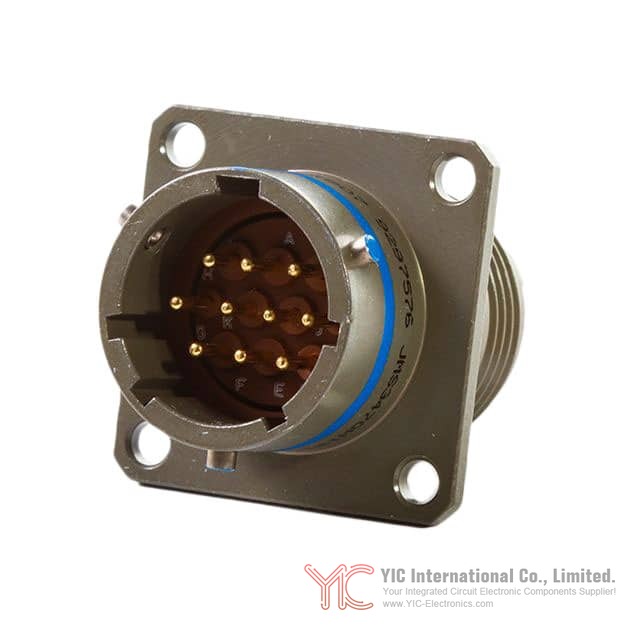
MS3476L14-18P Image

View larger Image

Image may be representation.
See specs for product details.

MS3476L14-18P

Manufacturer Part Number: MS3476L14-18P
Manufacturer/Brand: Conesys
Part of Description: CONN PLUG MALE 18POS GOLD CRIMP
Datasheets: MS3476L14-18P.pdf
RoHs Status: Lead free / RoHS Compliant
Stock Condition: 37647 pcs Stock
Ship From: Hong Kong
Shipment Way: DHL/Fedex/TNT/UPS/EMS

Request Quote

Please complete all required fields with your contact information.Click "SUBMIT REQUEST" we will contact you shortly by email. Or Email us: Info@Y-IC.com.

Part No.
Quantity
Target Price(USD)

Inquiry Online

  • Contact Name
  • Company
  • E-mail
  • Phone
  • Message
  • Verify
  • Specifications
  • QC & Packaging
  • Shipping
  • Payment
  • Part NumberMS3476L14-18P
  • ManufacturerConesys
  • DescriptionCONN PLUG MALE 18POS GOLD CRIMP
  • CategoryConnectors, Interconnects > Circular Connectors - Circular Connector Assemblies
  • Part Status37647 pcs Stock
  • Voltage Rating-
  • TerminationCrimp
  • Shielding-
  • Shell Size, MIL-
  • Shell Size - Insert14-18
  • Shell MaterialAluminum Alloy
  • Shell FinishElectroless Nickel
  • SeriesMilitary, MIL-DTL-26482 Series II
  • Primary MaterialMetal
  • PackageBox
  • OrientationN (Normal)
  • Operating Temperature-55°C ~ 200°C
  • Number of Positions18
  • Mounting TypeFree Hanging (In-Line)
  • Mounting Feature-
  • Ingress Protection-
  • Features-
  • Fastening TypeBayonet Lock
  • Current Rating (Amps)-
  • Contact Finish Thickness - Mating50.0µin (1.27µm)
  • Contact Finish - MatingGold
  • Connector TypePlug, Male Pins
  • Color-
  • Base Product NumberMS3476L14

QC (Quality Warranty)

All products are carefully inspected before shipment according to our Quality Management practices. We ensure each part is genuine, meets specification requirements, and is functionally checked against original datasheets.
Our quality process supports reliable part performance and minimized risk of defects in customer applications.

Visual Inspection X-Ray Analysis Decapsulation Analysis Spectrometer Dimension Verification Dimension Verification Dimension Verification

Packaging

ESD Protection & Handling

All ESD-sensitive components are handled under anti-static control procedures.
Products are sealed in ESD-safe packaging to prevent electrostatic damage.
Proper labeling is applied for identification and traceability.
This ensures product integrity during storage, handling, and shipment.

Global Shipment by DHL/FedEx/TNT/UPS

Delivery time
Deliverytime will need 2-4days to most of country all over the world for DHL/UPS/FEDEX/TNT.
Shipping fees reference DHL.
1). You can offer your express delivery account for shipment, ifyou haven’t any express account for shipment, we can offer our account inadvance.
2). Use our account for shipment, Shipment charges(ReferenceDHL, Different Countries has different price.)

Shipment charges: (Reference DHL)
Weight(KG) Price(USD$)
0.00kg-1.00kg USD$60.00
1.00kg-2.00kg USD$70.00
2.00kg-3.00kg USD$80.00

More details: https://www.yic-electronics.com/shipment-way.htm
Please feel free contact us. Send any inquires or question toour Email Info@YIC-Electronics.com
We can do the best to you. Thank you very much your support.

Payment Way: Wire Transfer = Telegraphic Transfer(T/T) or PayPal or Western Union

Wire Transfer (T/T)

Our HSBC bank name: The Hongkong and Shanghai Banking Corporation Limited (HSBC Hong Kong)

Benefit Company Name: YIC International Co., Limited
Bank charges and payment account details, please click "Payment Way".

Western Union


Complete payment by Western Union.
Step 1. Go to your local Western Union branch, or go to their website (www.westernunion.com)
Step 2. Follow their instructions.


Bank charges and payment account details, please click "Payment Way".

PayPal Account:

PayPal Golden Key Supplier

PayPal Account:
PayPal Account ID: Info@YIC-Electronics.com
Company: YIC International Co., Limited

If you want to pay via Credit Card, please choose "Pay with my PayPal account" to continue by paypal.(www.paypal.com)
Bank charges details, please click "Payment Way".

User Review

  • Driv***stemsDE

    This was purchased for servicing a large motor drive. After installation, switching waveforms looked normal and the unit completed our load test successfully. Packaging also protected the terminals well.

    September 21th, 2026

  • Bits***amBen

    Used the XC6SLX45 on a custom acquisition board with several parallel interfaces. Configuration was successful and the design has been running through overnight tests without errors.

    September 18th, 2026

  • Auto***rdRepair

    Exactly the MCU we needed for an automotive electronics repair. Programming and verification completed successfully, and the repaired controller has been stable on our test bench.

    September 10th, 2026

  • Powe***nch_NL

    This module went into a high-power inverter repair. Mounting and connections matched the original unit, and it handled our initial load tests without abnormal temperature rise. So far, very satisfied.

    September 1th, 2026

  • DCPo***Guru

    Designed a synchronous buck converter around this controller. Efficiency was impressive and voltage regulation remained very stable under changing loads.

    August 24th, 2026

  • Broa***stLab

    Used this crosspoint switch in a video distribution project. Signal integrity stayed excellent across every channel we tested.

    August 20th, 2026

  • Mich***Rowe

    Everything functions correctly and configuration was straightforward. I would have liked better protective packaging, but the device itself works perfectly.

    August 11th, 2026

  • Kevi***rshall

    Still a dependable MCU for maintaining older equipment. Programmed without problems and everything worked exactly like the original device.

    August 5th, 2026

  • Anal***uilder

    The DAC provides clean output and repeatable accuracy. Used it in a precision signal generation project with excellent results.

    July 28th, 2026

  • Etha***le

    I used this precision reference in a laboratory measurement board. Voltage stability was excellent, and drift stayed very low during several days of continuous testing. Definitely a quality analog component.

    July 22th, 2026

  • Sign***lockGuy

    Accurate crystal with stable frequency output. Worked perfectly as the timing source in a low-power embedded design.

    July 14th, 2026

  • Powe***idBuilder

    This hot-swap controller performed exactly as expected. Startup behavior was smooth and protection functions worked correctly during testing.

    July 6th, 2026

  • Yosh***_Engineer

    Used this instrumentation amplifier in a precision signal conditioning circuit. Low noise and stable gain characteristics made integration easy.

    July 2th, 2026

  • Taku***Ishikawa

    Used this IGBT module in a motor drive system. Power handling capability is impressive and the module remained reliable during repeated load testing.

    June 22th, 2026

  • Netw***Builder_UK

    Installed this Ethernet controller in a custom networking platform. Driver support was good and network communication remained stable during long-term testing.

    June 18th, 2026

  • Kent***orimoto

    Used this processor in a wireless networking project. Stable operation and good integration with existing software tools. Performance is sufficient for embedded communication applications.

    June 9th, 2026

  • Oliv***ughes

    Good capacitor quality. Used in a power supply rebuild and measured values were close to spec. No issues after several days of continuous operation.

    June 5th, 2026

  • Kevi***rner

    Very good MCU for legacy embedded projects. I used the LPC2387FBD100 in an industrial control board replacement and it integrated more smoothly than expected. Ethernet and peripheral support were enough for our needs. Been running continuously for over a week without instability.

    May 25th, 2026

  • Nath***ill

    Good supervisor IC for automotive power systems. Reliable reset behavior.

    May 19th, 2026

  • Jack***III

    Good price

    May 15th, 2026

  • Davi***ung

    Good SoC for networking applications. Stable signal processing and low power consumption.

    May 6th, 2026

  • Andr***ee

    Overall is good

    April 28th, 2026

  • Emil***ark

    Accurate frequency output for timing circuits. Works well in low-power signal designs.

    April 23th, 2026

  • Jose***Dong

    Quick response and clear answers.

    April 16th, 2026

  • Marc***echLab

    Excellent quality. All chips passed testing and showed consistent electrical characteristics.

    April 7th, 2026

  • Circ***MasterX

    Good packaging and fast shipping. Performance is stable, but I wish there was clearer labeling on each component.

    April 2th, 2026

  • SamT***Reviews

    Excellent ICs. Used them in a communication module and performance was stable.

    March 27th, 2026

  • Kevi***.

    Good quality parts. No failures during testing.

    March 17th, 2026

  • Bria***.

    Good

    March 13th, 2026

  • Mari***.

    Superb performance.

    March 2th, 2026

  • Emma***

    Excellent ICs for DIY projects. Came well-packaged, genuine parts, and all tested good on my bench. No fails on 50 pieces.

    February 26th, 2026

  • Gadg***an123

    Good

    February 10th, 2026

  • Quan***PartsLab

    Great service

    February 6th, 2026

  • Vect***upplyChain

    The sales rep was professional and responsive.

    January 27th, 2026

  • Puls***vePurchasing

    Components were packed carefully with anti-static protection and cushioning. Everything arrived in good condition.

    January 23th, 2026

  • Pixe***ocure

    Components were packed well. Appreciated the attention to detail.

    January 13th, 2026

  • Byte***dgeBuyer

    Good Quality & Fast Response

    January 5th, 2026

  • Circ***AtlasGlobal

    JUST WHAT I WANT

    December 30th, 2025

  • Allo***taImports

    Very professional

    December 26th, 2025

  • Apex***i

    Quick response and prompt shipping

    December 19th, 2025

  • Hexa***e Circuits

    We were surprised by how quickly our order was processed. From inquiry to delivery, everything was smooth. A trustworthy IC distributor with good stock levels.

    December 11th, 2025

  • Core***se Inc.

    Good customer service

    December 2th, 2025

  • Skyl***Drew

    Delivered ahead of schedule.

    November 28th, 2025

  • Byte***ad

    We purchased a batch of XC6SLX25T-2CSG324C from yic-electronics. Clean markings, fresh 2024 date codes, and antistatic packaging—service was efficient and polite.

    November 17th, 2025

  • avl_***rcing_julia

    Smooth checkout and same-day ship via FedEx. Parts arrived dry-packed, correct MSL labels, and fresh date codes.

    November 13th, 2025

  • Liam***hnson

    Price is good. Order processed quickly, and tracking provided the same night.

    November 3th, 2025

  • Yuko***kamura

    Prices were reasonable compared to other brokers. One reel had minor box damage, but the inner pack was intact.

    October 31th, 2025

  • Opti***

    Excellent prices and top-notch customer service. Even the standard shipping was surprisingly fast. Components were well-packed and genuine. Totally satisfied with the purchase.

    October 21th, 2025

  • Thom***Gray

    Clear communication and on-time delivery.

    October 15th, 2025

  • Aaro***ughes

    Excellent supplier. Great communication and reliable service throughout the process.

    October 9th, 2025

  • Auro***hip

    Good experience overall. The order was processed smoothly, packaging was secure, and the delivery time was acceptable.

    September 29th, 2025

  • Jimm***

    I had a great experience with this company. They were very professional and efficient, and they had the obsolete parts I needed in stock. Once payment was processed, the delivery was quick—my goods arrived within two weeks. The customer service was friendly professional, with seamless communication throughout. Overall, everything went smoothly, and I would definitely recommend them.

    September 19th, 2025

  • Jaso***in

    The purchase was easy and fast. Polite and helpful seller, great price.

    September 8th, 2025

  • NeoB***

    Schnelle Lieferung, Produkt entspricht der Beschreibung, hochwertige Verarbeitung, stabile Funktion, alles passt perfekt, sehr zufrieden mit dem Kauf.

    September 2th, 2025

  • Tobi***

    Quick response, good price and clear communication. Very satisfied with the service

    August 28th, 2025

  • Zóc***Nights

    Not bad

    August 19th, 2025

  • 3174***41@gmail.com

    Bought once to know that YIC electronic components quality is good, and the price is not expensive, very affordable, fast delivery!
    Really recommend buying electronic components here!

    April 14th, 2025

  • Yush***nagahata

    YIC is an excellent company.
    The deliverry time is fast, and we find it very usueful for procuring electronic components.
    We look forward to continuing our relationship in the future.
    Go YIC! Keep up the great work!

    February 20th, 2025

  • SAMI*** INSTALLATION

    Fantastic! Shure I would buy again with YIC

    January 23th, 2025

  • Aadh***x

    The experience with YIC International was great. They not only provided support for the proposed parts but also proactively suggested additional parts that could be useful for us. They have reviewed all the parts properly and corrected our requirements. The delivery and other logistical support were excellent.

    January 22th, 2025

  • Ke*

    A Reliable and Trustworthy Partner
    Received original, high-quality components with fast shipping from YIC electronics.

    November 25th, 2024

  • Nana***risnawan

    Great component supplier, a place that easy to find electronics parts at a good price and delivery.

    August 6th, 2024

  • Alge***n Gholson

    Great products, fast delivery.
    The quality and service of YIC Electronics' components are at the top of the industry. Highly recommended.

    February 20th, 2024

  • Frey***.

    Our partnership with YIC Electronics has been exceptionally satisfying. Their unwavering commitment to outstanding customer service, coupled with their highly competitive pricing and unwavering dedication to top-notch, high-performance product quality, has consistently impressed us. YIC Electronics stands out as a true industry leader in every aspect of their service. Their swift and efficient logistics feedback further underscores their professionalism and reliability.

    August 25th, 2023

  • Jo C***n

    High Quality Products!
    I received genuine, high-quality electronic parts. Thank you YIC electronics.

    August 12th, 2023

  • Edwa***W.

    Yic-electronics suppliers are top notch quality and consistent reliability, I have generated several orders from their website and their service has exceeded expectations in providing electronic components for our business needs.

    August 6th, 2023

  • Anna***

    Yic-electronics is a good partner for our company, we have been cooperating with each other for 4 years, and the cooperation is all smooth and there is no dispute about the goods. Our latest transaction with Yic-electronics happened a month ago, and the process was very smooth, thanks to Yic-electronics's help!

    June 17th, 2023

0 Articles

Post a Review

Hello , welcome to comment on this product
Rating *
5.0

Please limit the remark to 500 words

Your personal information will be hidden

FAQFrequently Asked Questions

  • What are the key design considerations when integrating the MS3476L14-18P into a high-reliability aerospace or defense application? The MS3476L14-18P is a MIL-DTL-26482 Series II circular connector designed for demanding military environments. When integrating this 18-position plug into aerospace or defense systems, consider that the bayonet lock fastening provides secure mating in vibration-prone applications, while the crimp termination requires proper tooling and training to ensure reliable contact resistance. The aluminum alloy shell with electroless nickel finish and 50µin gold contact plating supports extended service life in corosive environments. Operating temperature range of -55°C to 200°C allows deployment across wide altitude and thermal profiles. Verify that your system's connector receptacle matches MIL-DTL-26482 Series II specifications to ensure proper engagement and mating force characteristics.
  • Can the MS3476L14-18P be used as a direct replacement for older circular connectors in legacy military systems, and what compatibility issues might arise? The MS3476L14-18P can serve as a replacement for other MIL-DTL-26482 Series II 18-position connectors from the same shell size (14-18), provided that the original design used crimp termination and bayonet locking. However, compatibility depends on several factors: verify that contact pin assignment and signal routing match your legacy system's pinout; confirm that the replacement connector's shell material and finish meet your original system's environmental specifications; and ensure mating receptacles are not from an incompatible series or shell size. If the legacy system used solder cup termination or a different fastening method, the MS3476L14-18P will not be a drop-in replacement. Additionally, if your system relies on shielding or specific grounding paths through the connector shell, validate that the new connector's grounding scheme aligns with your application.
  • What specific challenges should engineers address when transitioning from MS3476L14-18P connectors to alternatives like TE Connectivity or Amphenol equivalents in production? Transitioning from the MS3476L14-18P (Conesys) to alternative MIL-DTL-26482 Series II suppliers such as TE Connectivity, Amphenol, or Radiall requires attention to several design and procurement factors. While these alternatives maintain electrical and mechanical compliance with MIL-DTL-26482, manufacturing tolerances, contact plating thickness consistency, and crimp contact resistance can vary between suppliers. Test the new connector's mating force, contact retention, and pull force before full production adoption, as differences in spring tension and contact geometry may affect cable strain relief requirements. Verify that pin assignment and shell polarization keys are identical across manufacturers, and confirm that your existing crimping dies and tools are compatible with the alternative supplier's contact geometry. Supply chain lead times and minimum order quantities often differ significantly; plan procurement accordingly. Additionally, some suppliers may offer extended temperature ratings or enhanced shielding options not present in the MS3476L14-18P, which could impact cost and availability.
  • How does the crimp termination of the MS3476L14-18P affect overall system reliability compared to solder cup or printed circuit board mount alternatives? The MS3476L14-18P uses crimp termination, which creates a cold-welded joint between the contact and the wire conductor. This approach offers several reliability advantages over solder cup termination in high-vibration or thermally cyclic environments: crimp joints eliminate thermal cycling stress on solder joints, reducing fatigue failure risk in applications experiencing wide temperature swings from -55°C to 200°C. Crimp contacts also provide superior vibration resistance due to the absence of britle solder joints. However, crimp reliability depends critically on proper wire preparation, correct crimp tool calibration, and operator training. Inadequate crimp pressure or wire gauge mismatch can result in high contact resistance or intermittent connections. For applications requiring board-mount flexibility, the MS3476L14-18P's free-hanging in-line configuration is not suitable; instead, consider backshell-integrated solder cup variants from the same series. Comparative testing between crimp and solder termination in your specific thermal and vibration environment is recommended before design finalization.
  • What are the contact resistance specifications and reliability implications of the50µin gold plating on the MS3476L14-18P? The MS3476L14-18P features 50µin (1.27µm) gold contact plating over nickel underplate. This thickness provides corosion protection and low contact resistance in most military applications. However, 50µin is at the lower end of military specification ranges; some high-reliability applications specify 100µin or greater for extended service life in salt spray or corosive environments. The nickel underplate prevents gold diffusion into the base contact material, maintaining contact resistance over time. Contact resistance values depend on mating force, contact geometry, and current-carrying capacity of your specific signal allocation. In applications where signal integrity and noise margin are critical, measure contact resistance variation across the18 positions after mating and environmental aging (salt spray, thermal cycling). Gold thickness degradation from fretting corosion may occur in connector pairs that experience frequent mating cycles or micro-motion in vibration environments. If your system requires contact resistance below 10 miliohms over the product's service life, conduct accelerated fretting and salt spray testing on production samples before design release.
  • Are there any EMI or shielding limitations with the MS3476L14-18P, and how should shielding be implemented in high-frequency or RF applications? The MS3476L14-18P is an unshielded 18-position circular connector, making it unsuitable for direct use in RF or high-frequency applications requiring full electromagnetic containment. If your application involves frequencies above 1 MHz or RF signals carrying sensitive modulation, you have several options: use the MS3476L14-18P with an external shielded backshell or connector shroud that provides 360-degree shielding and grounds to the mating receptacle shell; implement careful board-level shielding and signal segregation by allocating low-noise reference returns to specific contact positions; or specify a shielded variant from the MIL-DTL-26482 Series II family, which includes shielded insert designs. The aluminum alloy shell of the MS3476L14-18P can function as a partial Faraday cage if properly grounded, but without internal shell-to-shield contact provisions, crosstalk between adjacent signal paths may degrade high-frequency performance. Document your frequency content, impedance requirements, and crosstalk tolerances before finalizing the MS3476L14-18P in RF systems.
  • What are the thermal and mechanical stress considerations for the MS3476L14-18P when operating at the extremes of its -55°C to 200°C temperature range? The MS3476L14-18P's -55°C to 200°C operating range spans a 255°C delta, which creates significant thermal stress on materials and connections. The aluminum alloy shell exhibits different thermal expansion coefficients than steel backshells, cable jackets, and PCB materials, potentially inducing micro-motion at contact interfaces during thermal cycling. The crimp connection joint experiences repeated stress as the wire and contact expand and contract at different rates; over hundreds of thermal cycles, this can increase contact resistance or cause contact migration. At 200°C, the connector approaches the glass transition temperature of many polyamide insert materials; verify that the insert material specified for your MS3476L14-18P batch supports continuous operation at this temperature without mechanical crep. At -55°C, crimp joints become britle, and cable jackets may lose flexibility, increasing the risk of connector strain and intermittent connections under vibration. Implement thermal cycling tests (MIL-STD-1312-7 or equivalent) on your cable-connector assemblies across the full operating range before deployment. Additionally, apply strain relief boots and routing practices that minimize bending stress at the connector entry point during thermal extremes.
  • How does the bayonet lock fastening of the MS3476L14-18P affect mating and unmating procedures compared to threaded coupling? The MS3476L14-18P uses bayonet lock fastening rather than threaded coupling, offering distinct operational and design trade-offs. Bayonet mating requires 1/4 turn or less and generates axial mating force automatically without user rotation, making it suitable for field environments, rapid reconfiguration, or applications with gloved hand operation. This fastening method reduces mating time and eliminates risk of cross-threading. However, bayonet locks can disengage accidentally if exposed to vibration without secondary retention; military applications often mandate safety wires or captive fasteners through the receptacle coupling ring to prevent accidental disconnection. The mating force profile is sharper than threaded coupling, potentially causing shock loads to cable assemblies during engagement or disengagement. If your application involves frequent mating-unmating cycles (more than 500 cycles), validate that the bayonet locking cam and receptacle groove do not show wear or play after endurance testing. Additionally, bayonet-locked connectors require specific mating orientation alignment; ensure that connector keying and shell polarization prevent improper mating that could damage contacts.
  • What is the relationship between shell size '14-18' designation for the MS3476L14-18P and contact capacity or pin count limitations? The shell size designation '14-18' on the MS3476L14-18P does not directly encode the18-position pin count; rather, it identifies the physical shell diameter and insert interface according to MIL-DTL-26482 Series II standards. Shell size14 accommodates up to 18 contacts in a standard insert arrangement, while shell size 18 accommodates larger pin counts (up to 37 or more). The '14-18' designation indicates this connector uses a size-14 shell body. The contact pitch and spacing within the insert determine actual pin count and current-carrying capacity per contact. When evaluating the MS3476L14-18P for a new design, understand that pin count alone does not dictate available current per position; contact gauge and material must be considered. If your application requires future expansion beyond 18 contacts without changing the shell size, migration to a size-18 shell becomes necessary, requiring complete connector redesign. Verify insert contact capacity ratings against your signal and power distribution requirements before finalizing the design.
  • Does the electroless nickel shell finish of the MS3476L14-18P require any special handling, storage, or maintenance to prevent corrosion? The electroless nickel finish on the MS3476L14-18P shell provides corosion resistance and is typically free of cadmium plating used in older military connectors. However, electroless nickel can undergo localized corrosion if exposed to chloride-rich environments (salt spray, marine applications) without protective measures. Storage in high-humidity conditions (above 70% RH) or direct salt fog exposure may initiate white or black corrosion products on the shell surface over months or years. To maintain connector integrity, store the MS3476L14-18P in dry environments with desiccant, and apply protective coatings (such as light machine oil or conformal coating) if long-term outdoor or salt-spray-prone storage is necessary. Before mating, inspect the shell and contacts for any corosion products; light corrosion can be cleaned with isopropyl alcohol and soft brushes. If your application involves continuous marine or chemical plant environments, request additional protective plating options such as gold or chromate conversion coating during procurement. Periodic inspection of mated connector pairs under thermal cycling in salt-spray conditions is recommended for critical systems with service life exceeding five years.
  • What are the specific crimp wire gauge and contact pin requirements for the MS3476L14-18P, and how do undersized or oversized conductors affect long-term reliability? The MS3476L14-18P uses crimp contacts sized for specific wire gauges, typically ranging from 20 AWG to 12 AWG depending on contact variant selected during procurement. Undersized conductors (larger gauge number, smaller diameter) result in insufficient crimp depth and contact pressure, leading to high contact resistance, fretting, and intermittent connections within months of operation. Oversized conductors cause excessive crimp stress, potentially deforming or breaking the contact barrel, and may cause insulation damage during crimp tool closure. The correct approach is to identify the exact contact part number specified for your MS3476L14-18P connector, then use crimp tooling specifically calibrated for that contact and wire gauge combination. Verify tool calibration using pull-force test samples before production crimping. Mixed wire gauges within a single connector assembly should be avoided; if multiple gauges are necessary, specify different contact sizes and clearly label pin assignments. After production crimping, perform pull tests and continuity measurements on a statistical sample (5% or greater) of assemblies to catch tooling drift or operator error. Inadequate crimping is a leading cause of field failures in military connector applications; investment in proper training and process control is essential.
  • Can the MS3476L14-18P be used in high-altitude applications above 50,000 feet, and what environmental derating should be applied? The MS3476L14-18P can be deployed in high-altitude applications above 50,000 feet, but several environmental derating factors apply. At extreme altitude, atmospheric pressure drops below 0.5 psia, reducing air cooling and increasing corona discharge risk for high-voltage signals. While the MS3476L14-18P does not specify voltage ratings in its published parameters, if your signal content includes DC voltages above 100V or AC signals above 50V RMS, arcing or corona may occur in the low-pressure environment between contact pins or between pin and shell. Implement increased crepage and clearance distances, or apply conformal coating over the insert contacts to suppress corona. Temperature extremes at high altitude also challenge the connector: external air temperatures can plunge to -60°C or lower, while internal electronics dissipate heat, creating steep temperature gradients across the connector assembly. Thermal stress on crimp joints and contact springs increases under these conditions. If your application involves sustained high-altitude operation, conduct thermal cycling tests at actual altitude range or in a vacuum chamber simulating the pressure and temperature profile. Additionally, moisture ingress becomes more likely in pressurized cabins or aircraft where humid air is recirculated; specify a backshell with moisture barrier or apply sealant over the insert contacts to prevent corosion.
  • What are the implications of the MS3476L14-18P's free-hanging in-line configuration for cable routing and mechanical strain management in vibration-heavy environments? The MS3476L14-18P's free-hanging in-line configuration means the connector is supported only by the cable itself, without a chassis-mount flange. This design allows flexible routing and rapid field replacement but places the full mechanical load of connector weight, cable tension, and vibration forces on the cable strain relief and crimp connection joint. In high-vibration environments (aircraft, vehicles, industrial machinery), the free-hanging mass of the connector induces repeating stress on the crimp joint, potentially causing fretting corrosion at contact interfaces or micromotion at the crimp barrel. To mitigate, use oversized strain relief boots (typically 1.5 to 2 times standard size), route cable with minimal bending near the connector, and support the cable at multiple points (every 12 to 24 inches) using clips or conduit. Avoid tensioning the cable in a way that creates sustained pulling force on the connector; instead, create loops or slack to absorb vibration shock. If your application requires the connector to be unmated and remated in the field, design cable routing to allow technicians to support the connector mechanically during disconnect to prevent shock loads. For extremely vibration-heavy applications (shock environments exceding 10G peak), consider upgrading to a panel-mount receptacle design with the MS3476L14-18P mated on a fixed jumper rather than free-hanging.
  • How does RoHS3 compliance of the MS3476L14-18P affect material selection, particularly regarding the aluminum alloy shell and contact finishes? The MS3476L14-18P is listed as RoHS3 compliant, meaning it contains no lead (Pb), mercury (Hg), hexavalent chromium (Cr(VI)), or other restricted substances above specified thresholds. Specifically, the electroless nickel shell finish must use nickel-phosphorus or nickel-boron compositions free of cadmium; older military connectors often used cadmium plating, which is now prohibited. The 50µin gold contact plating is RoHS-compliant when applied over a nickel underplate without lead softeners. However, RoHS3 compliance does not preclude use in aerospace or defense applications where lead-containing components may be permitted under exemptions. Verify with your procurement organization whether full RoHS compliance or controlled-substance exemptions are required for your program. Additionally, RoHS3 compliance status can vary by manufacturing lot; request documentation (Certificate of Compliance or Material Declarations) confirming that your specific MS3476L14-18P batch meets RoHS3 standards. If your design includes a mix of RoHS and non-RoHS components, document the decision and any risk mitigation measures, as supply chain audits may flag inconsistencies.
  • What are the contact resistance degradation mechanisms for the MS3476L14-18P over extended service life, and how should monitoring or maintenance schedules account for this? Contact resistance in the MS3476L14-18P increases over time through several degradation mechanisms: fretting corrosion occurs when mated contact pairs experience micro-motion due to vibration, thermal cycling, or mechanical stress, wearing away the gold plating and exposing the nickel underplate or base copper to oxidation. Gold oxide and nickel oxide layers form a resistive barrier, elevating contact resistance. Crep of the crimp connection also contributes; the contact spring force can relax over years at elevated temperatures, reducing mating pressure and increasing resistance. Contamination (dust, salt deposits, or condensation on connector surfaces) further increases resistance if moisture-barrier protection is inadequate. For critical systems with service life exceeding 10 years, establish a maintenance schedule that includes periodic unmating-remating cycles to disrupt oxide films and restore contact pressure, or use conductive lubricants rated for military applications (such as MIL-PRF-23827) applied to contacts before final mating. Implement in-service monitoring of signal quality, noise margins, or functional tests on connectors experiencing extended service life. If contact resistance exceeds 50 miliohms on any of the 18 positions, plan connector replacement or refurbishment before field failure occurs. Document baseline contact resistance values immediately after assembly for later comparison.
  • How should the MS3476L14-18P connector be integrated into systems requiring intermittent power disconnection or hot-swap capability? The MS3476L14-18P is a passive mechanical connector with no inherent hot-swap or power break-before-make functionality. If your system requires disconnect and reconnect of power or signal lines without disrupting other circuits, several design considerations apply. First, establish the electrical load and switching transient behavior: if power lines through the MS3476L14-18P carry significant current (>1A) and are disconnected under load, arc suppression measures must be implemented, such as RC snubbers across the contacts or external circuit breakers upstream of the connector. Second, the contact separation sequence matters; if the MS3476L14-18P's pin assignment allows signal ground to disconnect last, transient voltages may damage sensitive circuits downstream. Implement make-before-break logic by routing ground returns through longer contacts or using a secondary connector for ground continuity during the mating transition. Third, verify that the crimp contact springs maintain sufficient retention force across thermal and vibration stress to prevent partial disconnection during in-service vibration. Conduct repeated mating-unmating cycle testing (200+ cycles) with electrical load applied to validate that arc erosion and contact wear do not degrade performance. For true hot-swap applications requiring zero disruption, consider adding auxiliary connectors for sense lines or use an external switching relay controlled by a separate logic connector.
  • What procurement or specification documentation should be verified before ordering the MS3476L14-18P to ensure compatibility with legacy military systems? When procuring the MS3476L14-18P for integration into legacy military systems, verify the following documentation and specifications: confirm that the connector conforms to MIL-DTL-26482 Series II, not Series I or commercial variations. Request a Certificate of Conformance or test report confirming that the MS3476L14-18P meets MIL-DTL-26482 mechanical, electrical, and environmental test requirements, particularly contact resistance, mating force, and temperature cycling. Specify the exact contact size and wire gauge rating required for your application, as the base part number MS3476L14 may be offered with multiple contact variants. Verify the shell finish specification (electroless nickel thickness and RoHS compliance status) matches your system's environmental and procurement requirements. Request Material Declaration (MD) or Conflict Minerals reporting if your program requires it. Confirm lead-time and minimum order quantities with the supplier, as military-grade connectors often have extended procurement cycles or MOQ constraints. If the MS3476L14-18P is being substituted for a previous part number, conduct a formal engineering change order (ECO) and cross-reference the old and new part numbers in all drawings, BOMs, and test procedures. Legacy systems may reference older Conesys or DFM (now part of Conesys) documentation; ensure that current MS3476L14-18P specifications supersede obsolete revisions.